Weekend
Radio Click
Here for More Electronics Projects and
Tutorials By
Mike Maynard, K4ICY
A Curiously Narrow CW Audio
Filter
By Mike Maynard, K4ICY
If you're just getting
into CW and you are starting off with an older radio or
QRP set then you're sure to have run into the problem of
trying to pick out any given CW signal from a pileup. Modern
commercial radios come equipped with filters for
narrowing the audio passband and the digital signal processing (DSP)
models can do every trick allowed by virtual physics to
clean up unwanted noise.
The trouble you may be having is due to the bandwidth of your
receiver's audio passband which may be too
wide, so other nearby signals are competing for your ears.
What you need to do is just pick out one single CW signal.
This little accessory will add
the much needed narrow band filtering to
your radio's audio output!
The circuit is
(litterally) textbook, inspired from the ARRL Extra Class study
manual's
(Volume 8) pages on active filters and is an Active RC driven filter using Op amps.
It has
a narrow passband that will amplify only a desired
range or audio frequencies and reject others that may present QRM
& QRN interference.
It's small
enough to be tucked away inside of many older
rigs and the ouput is enough to drive a pair of headphones or a small
PM
speaker.
However, it must be
formulated and pre-constructed for a set passband frequency range, i.e;
700 Hz.
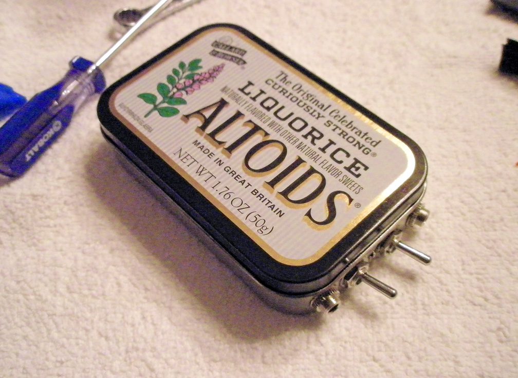
This project was stuffed into
a small Altoids® mint tin.
(Click
to enlarge photos)
Building your own
station accessories is a time-honored tradition of the Ham Radio hobby
and there's
more satisfaction and learning that comes from homebrewing a
device over that
of just ordering an "appliance" from an online distributor.
If you would like to construct your own gear such as this,
you should have some basic
knowledge of electronics, being familiar with IC's and audio
circuitry. If you're a ham, this should come naturally of
course. A lot of trial and error went into my own
construction of my CW filter and I do
not profess to being an engineer.
Operation
Operation couldn't be simpler: One audio
input jack accepts a patch cord from the radio and your headphone plug
into the other one. There are two switches, one to select
between activation of the circuit and bypass mode, and the other to
choose between two and four stages, or rather, ecause of the switch I
used, in the "OFF" position the filter is in
"Bypass Mode" and only a 220 µF capacitor sits on the line.
When
activated, the stage selector is kept at the halfway point at the
output of the 2nd 741 Op amp as this allows for much filtering but with
enough outside audio being passed through to be able to adjust the VFO
knob on the rig. When an incoming CW signal is set at
"zero-beat" you can then switch the
output to four-stage mode using all the Op amps. If the
received CW audio is clear or even piercing then the filter is
working. The only downside is, since this filter is extremely
narrow, some "ringing" (which
sounds like noise played underwater) may be produced.
The provided schematic
(below) has component values set to provide a frequency
response filter the incoming audio at around 750 Hz and the
"shoulder" of the response curve is wide enough to allow
frequencies 50 Hz in either direction with audibility. (700-800 Hz)
If you have a different sidetone on your rig other than 750
Hz, you'll
first need to zero-beat the signal in bypass mode and use
the RIT on your receiver to "fake" the received tone match 750 hz.
This will allow you to enjoy the benefits of the filter
without the math. So far, the low capacity generic 9 volt
dry-cell has provided filter
power for hours, the circuit's current drain is in the low mA's so I
can
imagine a good Alkaline battery lasting a long time.
If you use a Lithium 9 v battery, you can escape the risk of
battery
leakage and have a viable accessory that will stick around for years.
Suggested Steps in Construction
•
Study the
schematic
• Calculate the
parts needed, and then recalculate.
• Hunt for spare
parts and purchase the ones still needed...
Consider the cost of
parts together as this may cost more than a pre-built version.
• Build circuit on a protoboard first
as this will allow for changes and help
you determine the project's usefulness.
• Use construction method of your choice,
either with a perfboard or with a custom etched PCB from PCBWay.com
• Test every aspect of the board. An
oscilloscope is preferred but even a multimeter can be invaluable.
• Enclosure prep,
switch mounts and wiring. Can you make things compact but
easy to access and service?
• Finalization,
mounting and cosmetics - this is industrial design and a well-designed
product will get used more.
•
Consider additional
feature such as adding a gain amp at the end along with a volume
reducing resistor network potentiometer before the first capacitor to
address
operating level deficiencies.
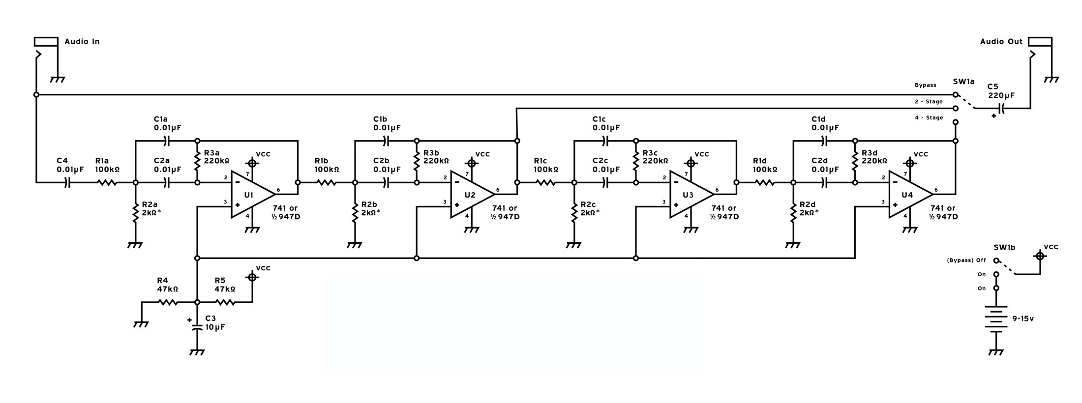
Schematic

The
layout is actually easier than it looks. There are just four of the
same filter cascaded.
Circuit Description
Standing on the "shoulders of giants," I, of
course, can't take full credit for this circuit, I used various
reference
sources such as the ARRL Extra Class License Manual, and a GL Tab book
on Practical OP Amp Circuits. The filter runs off of a 9 v-15
v power source and unbelievably draws only 3 mA. You
can either
use four individual 741 op amps ICs, or in my case, (2) 947D
dual op amps, but others
Op amp variations will work. The Op amps are
configured with a bandpass topology, using a Twin-Tee
Resistor-Capacitor network and the external components are what
determine the operational
characteristics of the amps and the quality (or effectiveness
level) so close tolerance
components must be considered.
C4 in front
decouples the incoming audio signal. R1 determines gain
and is compared to the +/- voltage reference input on
the non-inverting side (+), those values R4 & R5 must be equal but
do not have to be an exact value related to the rest of the circuit.
Cutting R1's value in half to get the value of R4 &
R5 will work
fine. C1
& C2
and R3 are
the resonance
tank that determine the center frequency. The active
bandpass frequency must be determined by R1-R3 so creating a variable
frequency response control is out of the question! R2 will thus
determine
the bandwidth to a degree and if only one stage is to be used, that may
be a nice feature. You can vary this
value to give you a controllable width of the final passband.
This project uses four
stages to hone in the passband and is quite
effective with CW signals. Using more stages will
subsequently add more filtering, but in the
bargain, a ringing will become more evident and eventually the
desired signal will distort beyond usefulness. The ringing on
this one is not too bad and if it is evident it sounds
more like a signal that was put under water. There
has to
be an increase in out-of-passband signal energy (other signals) to
cause this effect.
As you can see, the voltage
comparator network: R4 & R5 is
shared between all stages and cuts down on parts and connections.
C3: a 10µF electrolytic cap was included for AC signal
blocking to
prevent a spurious oscillation. A 100-400µF electrolytic cap
must precede the output to decouple the
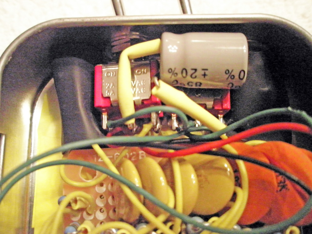
output. As far as functionality and controls are concerned,
this is the
builder's choice. I went with a DPDT switch for circuit
power, using the other side to bypass the audio when "OFF".
A SPDT switch is used to choose between the output for the
two stages
and a total four stages.
You can even talor the "envelope" of the passband by allowing the end
two phases to have a wider pass, letting in just enough outer-band
audio to keep you from getting lost when spinning the tuning dial on
your rig.
Concerning the chosen
resistor-capacitor values: first, if choosing
smaller cap values (like the 680 pF) will thus cause the resistor
values
to go up to satisfy the equation. When the resistance goes
up, the audio power going though will be cut
and your total volume gain will be small. You'll then have to
add another amplifier circuit such as an LM386 IC
based one to re-gain the audio volume. Higher values of caps,
like above 0.2µF will give you lower resistor
values, allow more audio power to run though, but will cause possible
distortion and too much current flow to the op amps. This is
why experimentation is suggested to be done on the breadboard
or in a simulation program like LTSpice
first.
I chose 0.01µF's since I had
a handful of them laying around. This
value works fine, but my final volume is a little low, and I cannot
allow too much AF volume from my rig before the filter becomes either
non-responsive or distorts with large signals. By using a
potentiometer for R2 AND using that part in series with a
low value resistor like a 500 ohm (to prevent a short) will allow you
to tweak the bandwidth and R2 value to match your sidetone
signal -
this may allow you to use fixed resistors. You can however use four
trim-pots if money is not an issue.
The formulas can be
found in the ARRL's
8th
Edition Extra Class License Manual on pages 6-7. (2007
issue... not sure about currently)
Also check this info out at Radio-Electronics.com...
where you can get some extra theory information.
C
will be both
C1 and
C2 in farads
F = Frequency in Mhz
Q =
(sharpness of the filter skirt) should be less than 10
G =
(Gain) should be 5 or less
R1 =
Q / G x 2 x π x F x C
R2 = Q / (2 x Q˛ - G) x 2 x π x F x C
R3 = 2 x Q / 2 x π x F x
C
• First choose a
capacitor value, 500 pF - 0.2 µF
• Choose a
frequency close to the "sidetone" of your transceiver. New rigs allow
you to set the frequency.
Applications such as CWget
are useful in detecting your side tone's frequency using your PC's
sound card.
• Calculate and
choose resistors close to those values. Use series or parallel values
where necessary.
• Start off with
one stage on the breadboard first.
• Use a variable
potentiometer for R2 with a value of at least twice the required
resistance or more to allow for tweaking.
• Measure this
value with your ohm meter to get fixed values. Use trim-pots for final
construction if desired.
On The
Breadboard
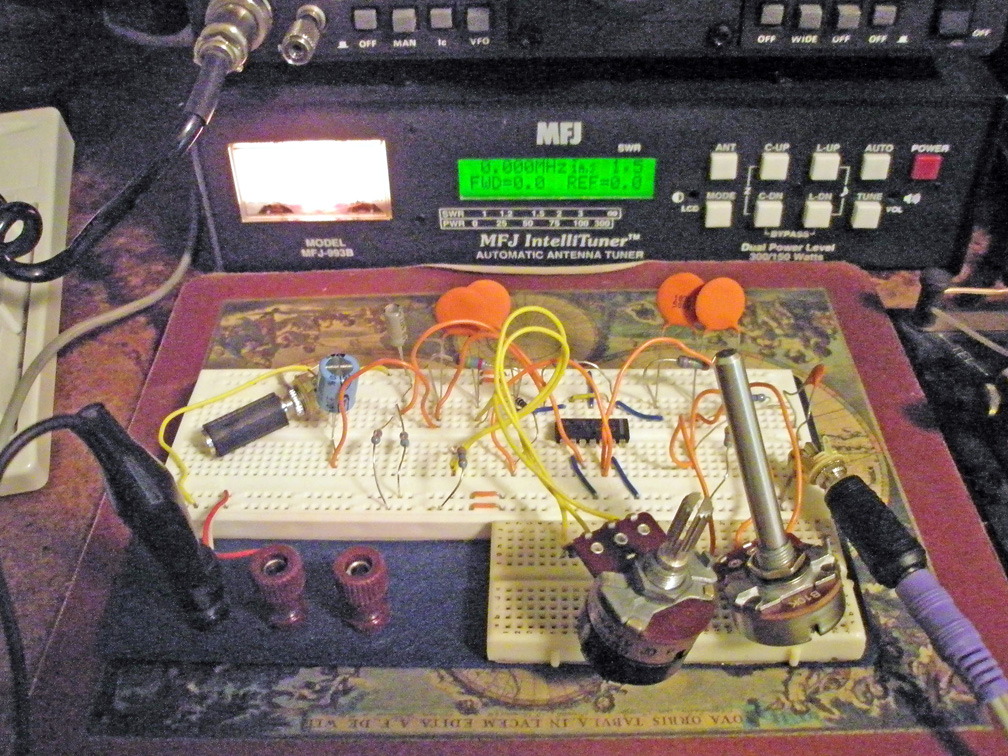
First one and then two stages
were
breadboarded and values adjusted with potentiometers.
On the breadboard is
where I delveloped my own version of a very common project.
By using
potentiometers on different parts of the circuit, my initial goal was
to make the frequency passband variable and not the bandwidth.
However,
the nature of the op amp and the twin-tee RC net required that many
values separately determine the center frequency. I had to
settle for a
close match to the 732 hz sidetone that my current rig produced.
The
passband would end up being 60-100 hz and would allow for deviation
anyway.
The whole
circuit in action with fixed resistors...
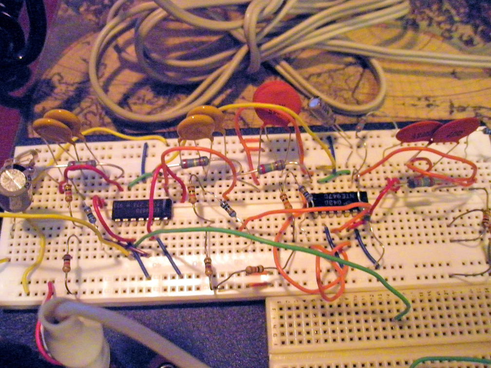
Here
is a good time to work out all the kinks.
The entire circuit was
re-constructed on the breadboard with fixed-resistor values that match
that of the potentiometers when adjusted.
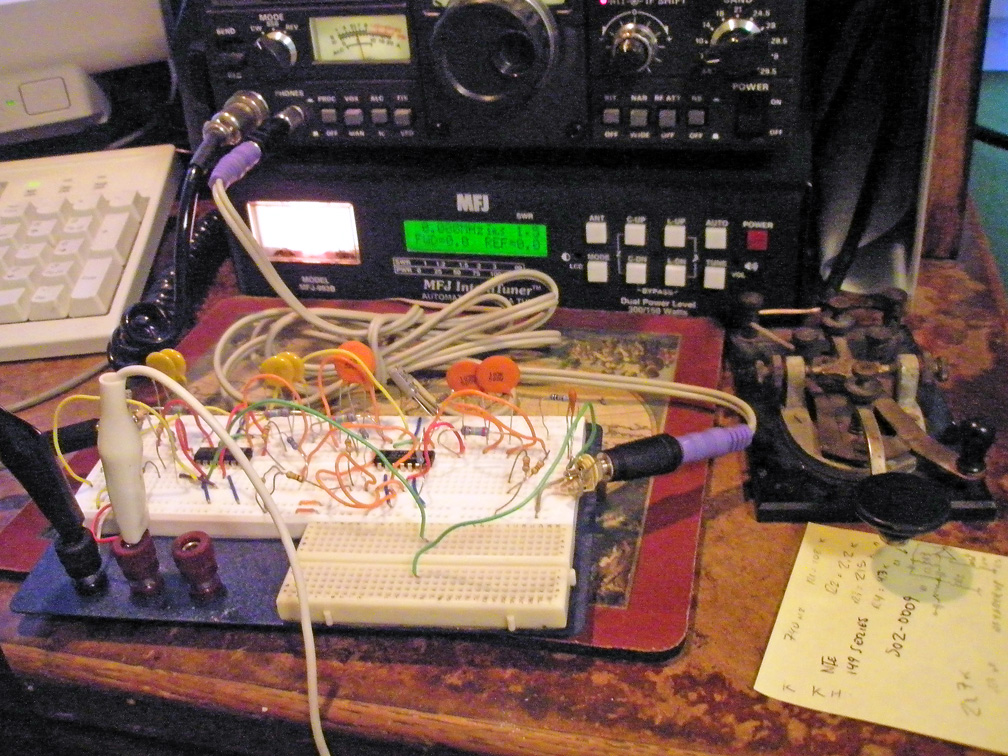
Project
shown connected to audio source.
Testing with PC
based audio anaylizer...
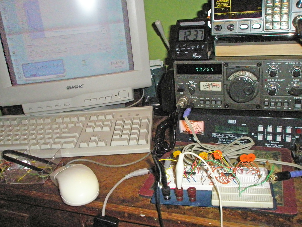
This
setup allowed me to get the values right where I wanted them.
Though nothing beats the equipment between your ears!
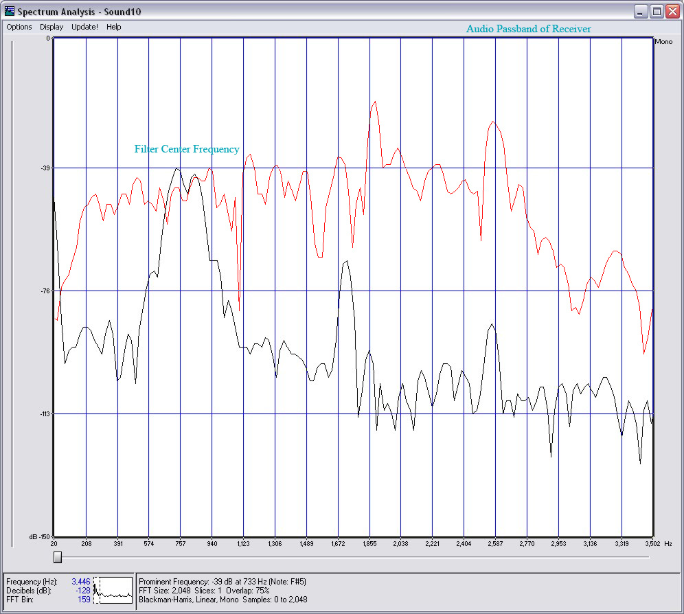
Testing revealed that the center
frequency was finally at 750 hz, there was the -6 dB
reduction knee at 718 hz and 782 hz and dropped off very rapidly after
that. There was 40 dB to 60 dB attenuation by 685 hz and 815
hz (roughly) and a 3 dB
gain on the center frequency. It was found that the noise
floor or overall noise of the stop bands
(ouside range) had a potent effect of desensitizing the filter. Sronger
signals caused distortion, so starting with a lower output AF volume
setting is suggested.
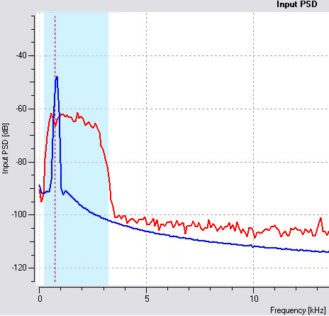
This
is a screen capture of the analyzer. The shaded area
represents the receiver's AF passband, the Red line is sampled from the
original audio signal and the Blue line is sampled from the
filter output. The transceiver's sidetone was used as the
test tone, and the noise
level was such that it very well buries the tone in the original audio.
Later, another test [on 05/17/08]
was done using a place on the 40 m CW band. Click
here to listen to an audio sample...
The Kenwood TS-130SE was placed in the 3 kHz wide SSB mode to allow a
lot of noise and adjacent signals in. In the sample you
should be able to barely hear the CW letter "D" (-..) in the audio,
this signal was pre-tuned to match the sidetone of the rig at roughly
732 hz. The filter set at 750 Hz would have no problem with
the sidetone. You will first hear the bypassed audio for a
few seconds, then with the
filter in four-stage operation, then in two-stage to allow more audio
in, then back to bypass mode.
The screen capture (below) was derived from parts of the audio sample
analyzed in SoundForge.
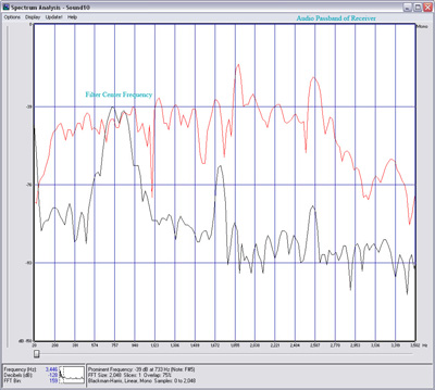
This
is a composite of SoundForge's spectrum analyzer's screen capture and
is a more comprehensive analysis of the accumulated audio component
amplitudes.
The Red line is sampled from audio that was directly from the
receiver
in Bypass mode on the filter and the Black line shows the filter in
action with all four stages.
This scan more reflects the more
extreme conditions of the audio sample; heavy QRM/QRN and a high noise
floor . The level of attenuation is impressive! There are two
curious anomolies that I would like to resolve. 1) The
extremely loud "Ker-Chunk" that occurs when the circuit is powered.
There's a large capacitor accross the audio output but there must be a
way to shunt or initially quell this artifact as it is unpleasant to
hear when constantly bringing the filter in and out. A build-up circuit
using a 2N7000 MOSFET and and timing capacitor and resistor could
initially sink audio to groung for a few ms during power up.
2) There seems to be some type of harmonic filter response
that is seen
in a broader spectrum, a byproduct of the simple RC configuration.
As
with any harmonic, the amplitude decreases as the frequency increases,
though this is a harmonic based on band passing and not a present tone
and occurs at evey 5 kHz interval, but also at 2.5 kHz & 1.7
kHz.
However this seems to be at and acceptable level as there is
no audible evidence
perceived. An additional low-pass filter element could
be dded.
Construction of the
circuit board...
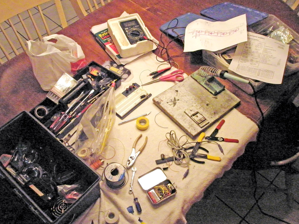
My ex-wife was never too
happy
when it was time to enlist the kitchen table into serving as a lab
bench...
Every
builder must determine what kind of construction and housing methods
are best for them and the use of the project. Good
construction techniques learned from "Elmer's" and from the manuals
are a must to taking pride in your work. Proper care must be
taken when working around larger 12 v power
supplies and RF shielding implemented around the final project.
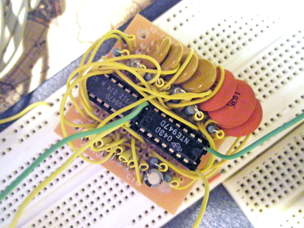
New circuit board attached to
breadboard for testing.
It's a
good idea to run a "smoke test" and test the circuit once soldered to
find any mistakes and maybe even adjust component values, as tolerances
and values can change
during installation, especially in a circuit where there's a bit of
interplay between stages. Shortening lead lengths and placing
components closer together can
augment stray capacitance values. The bottom of my prototype
board feels like it has about a 1/4 lb of lead! Note that
smaller capacitors can be used along with 1/4 watt resistors.
Amazon and eBay sell massive 600+ piece capacitor sets for
both electrolytic and ceramic for as little as $10. They're
not the best by far but can be used in non-timing critical places.
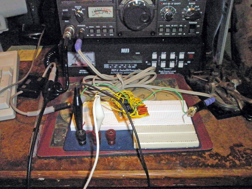
Testing back on rig shows
that the center frequency moved up 10 hz.
This is to be
expected and allows you to go back and augment parts.
Housing
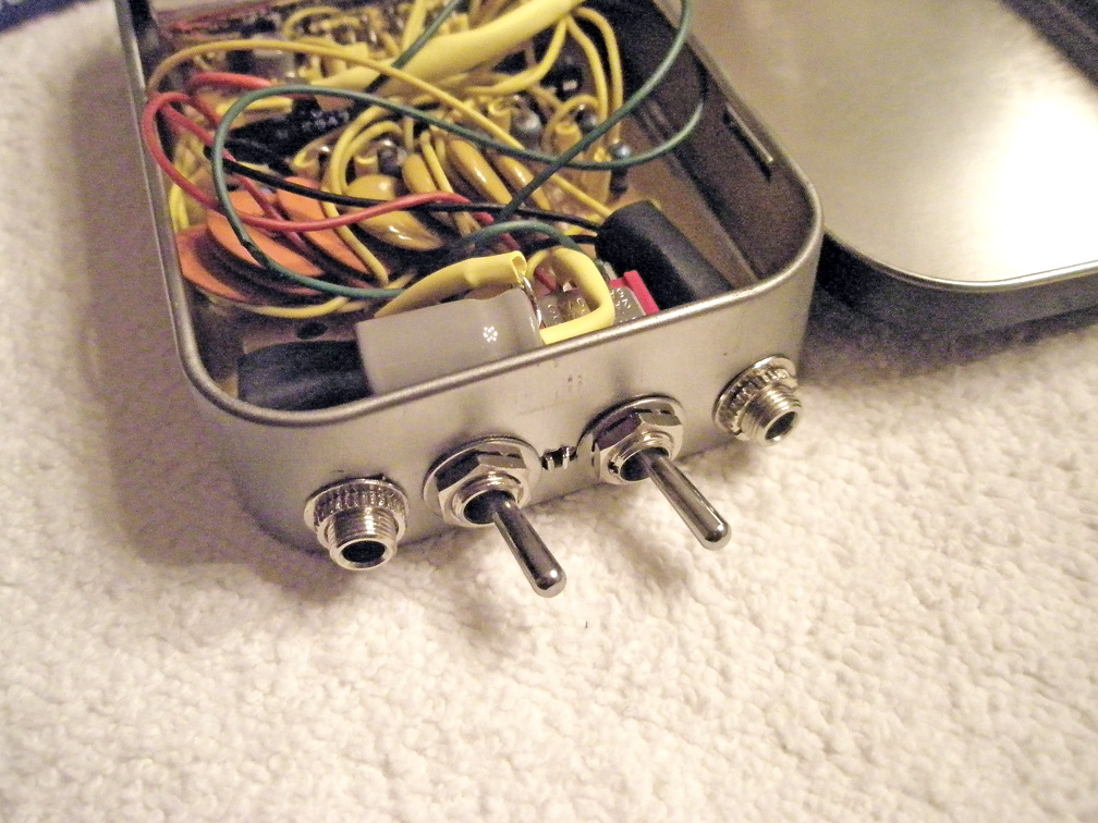
Holes drilled for switches
and jacks... then the circuit board was wired to the switches.
I chose a
small Altoids mint tin for the enclosure... of course I did, but I
really didn't know going into
this project, how much space I needed when the project was started.
I purchased the switches at the end for being small and
durable and I
had plans to use an exterior jack for power with Powerpole connectors
but discovered that a 9 v would fit neatly at the end. The
current drain is very low, so a dry-cell works quite a long
time. Ensure that if the container you are using has
conductive properties, either made of metal of anti-static plastic (I
bet you didn't know that) then use an insulator or a few strip of
electrical tape to keep the circuit joints and wire from shorting out.
The
outside of this container had some kind of clear paint which made it
mostly non-coductive.
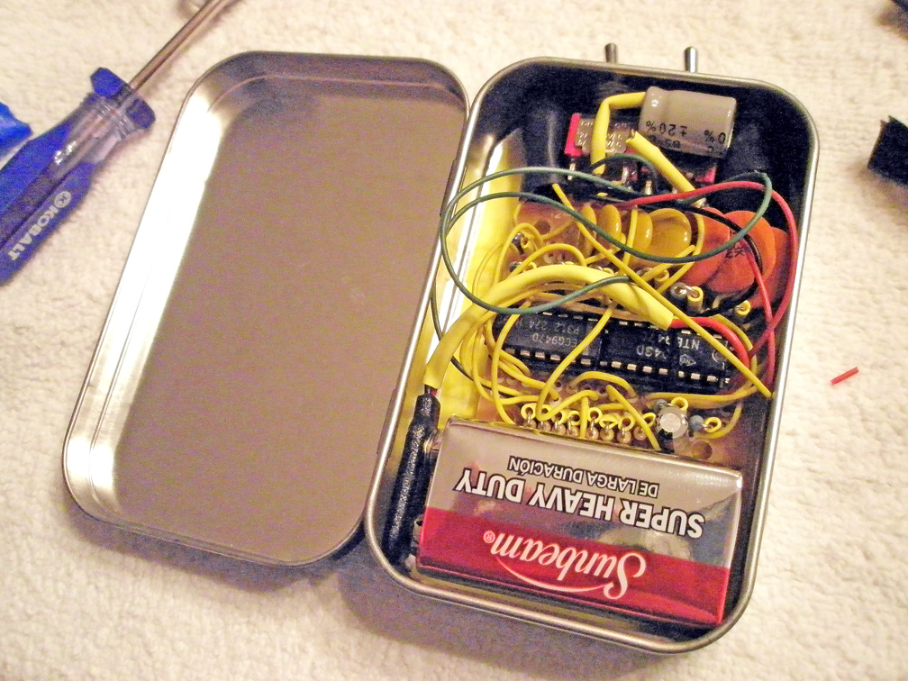
Everything fit neatly... This
was by accident I assure you!
The lid actually closed!
Providing an RF shielded compartment.
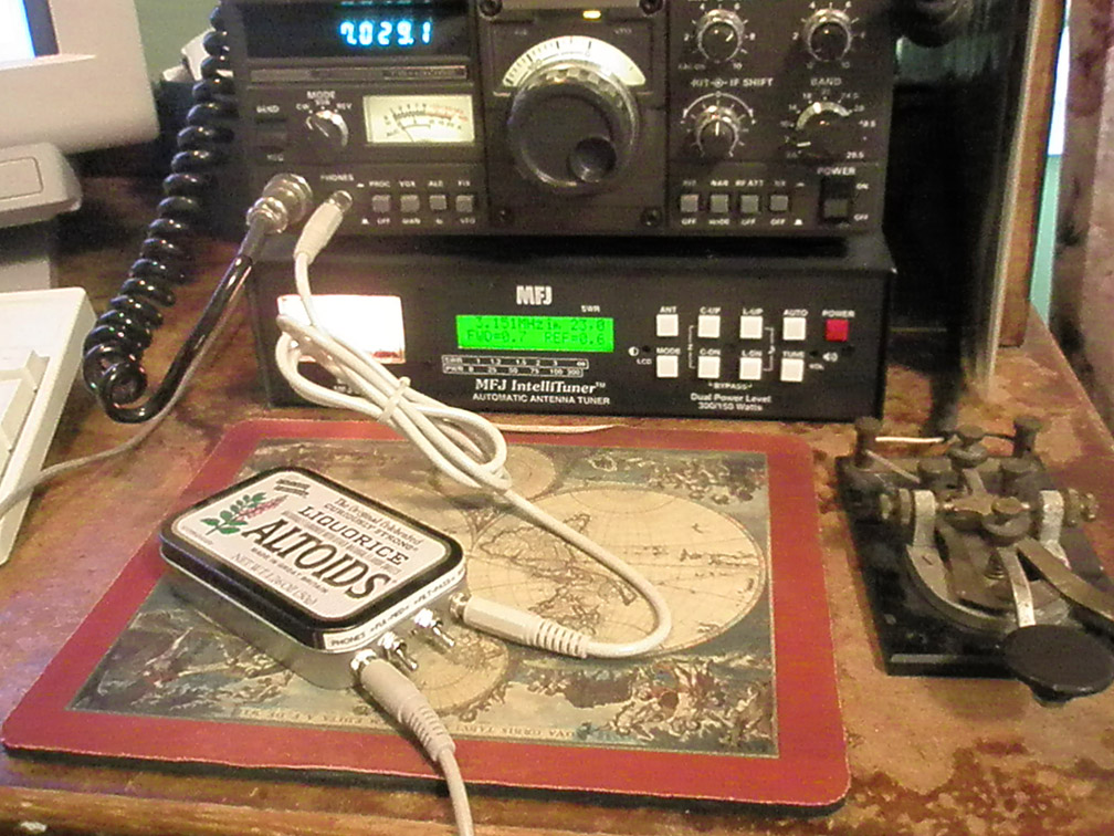
Labeled and attached for work
to the transceiver.
Now it's
ready to use, and work it did! I was amazed to be able to
both zero-beat onto another caller quickly and
be able to isolate just who I wanted all while cutting out all kinds of
noise, even the extreme noise produced by my computer equipment.
Good
Luck on your own projects! 73, De Mike Maynard K4ICY
SKCC #8600
Updated
06/02/20
(c)2020
Copyright - Michael A. Maynard, a.k.a. K4ICY
|