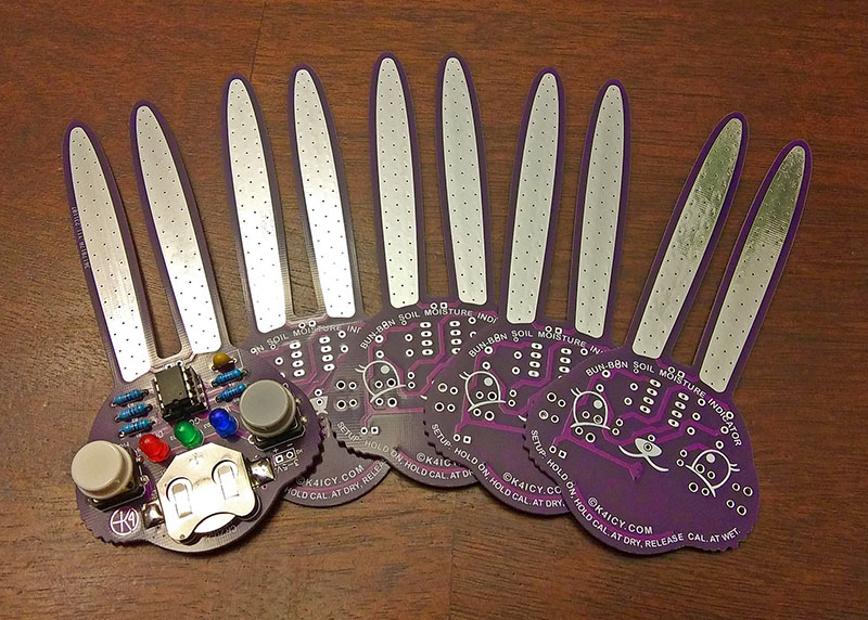
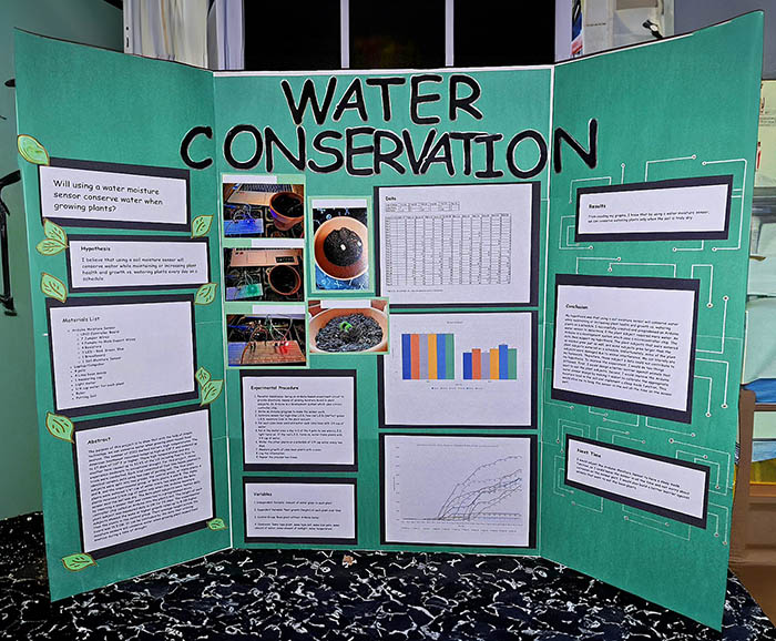
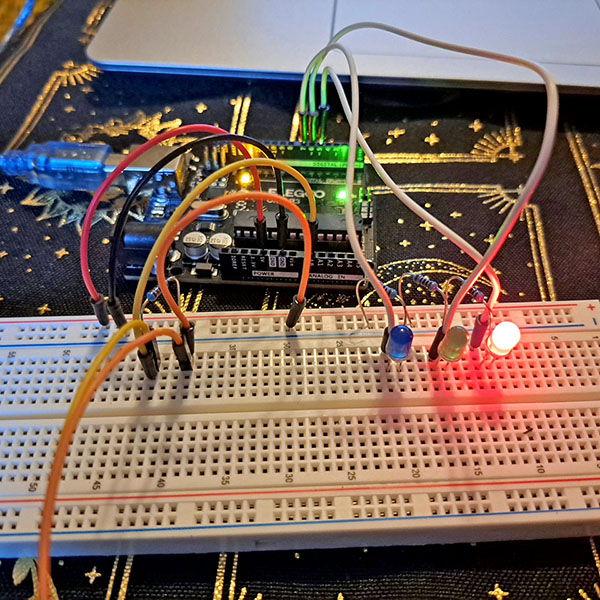
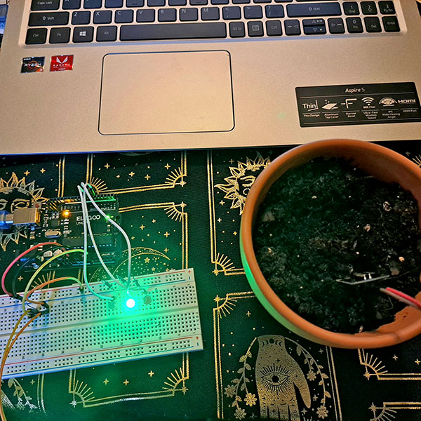
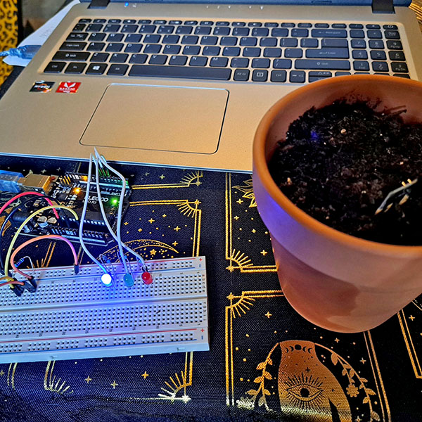
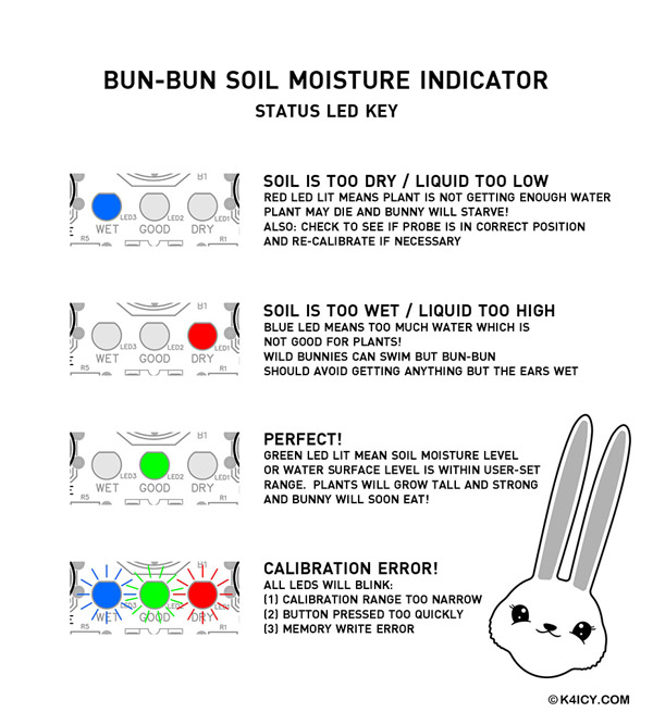
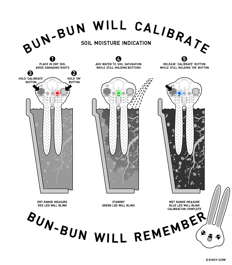
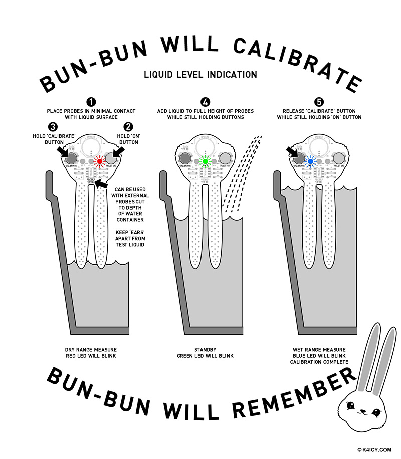
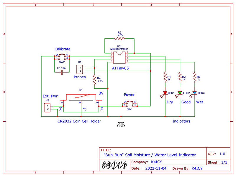
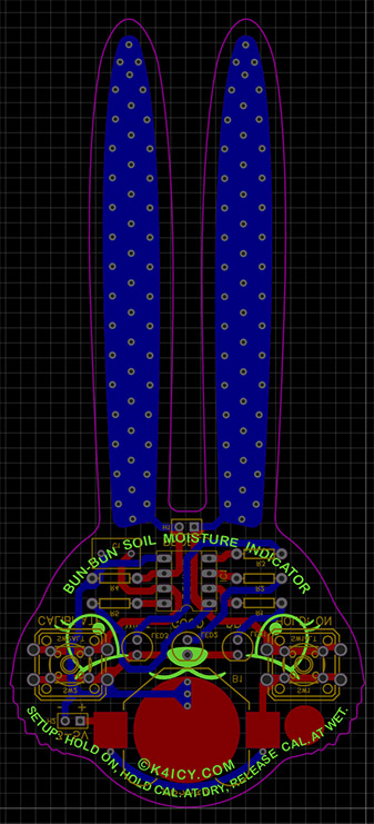
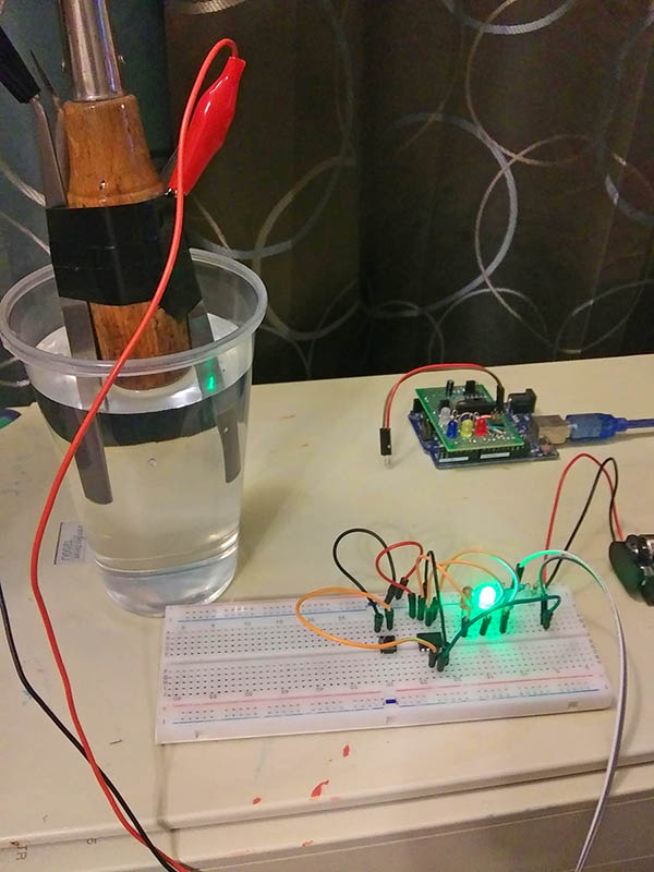
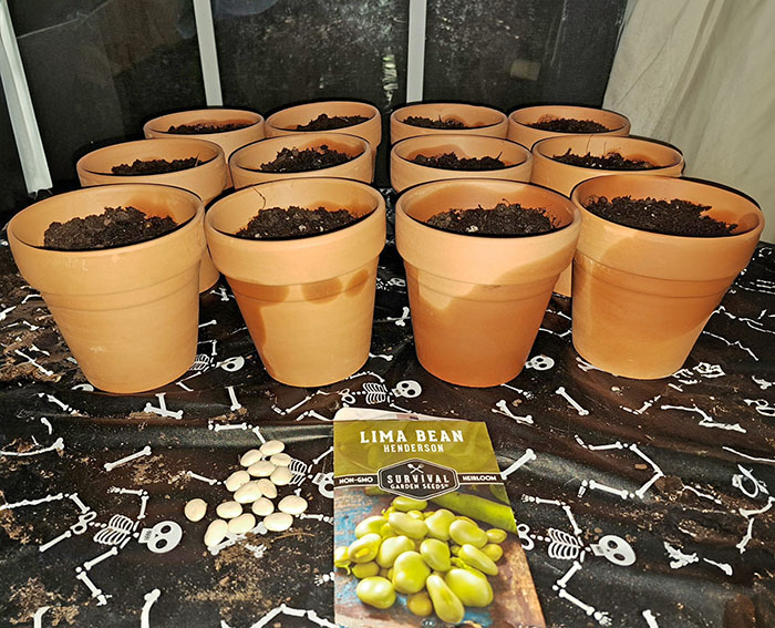
 Arduino Projects By Mike, K4ICY Arduino Projects By Mike, K4ICY Weekend Radio Click Here for More Electronics Projects and Tutorials By Mike Maynard, K4ICY Bun-Bun Soil Moisture Sensor This is a cute bunny face-shaped soil moisture and water level indicator using an Arduino-based ATTiny85 microcontroller, with sensor probe ears and calibration memory, running from a 2032 coin battery. . . The cheaper moisture sensors can be had like candy in bags of 5 or 10 from Amazon, eBay, AliExpress and other sources and are staples of beginner's Arduino learning kits. They generally consist of a small PCB (Printed Circuit Board) in which the major portion are two prongs covered with exposed electrode pads, and on the minor part, a comparator IC which is used to provide a logic 'high' or 'low' signal to any microcontroller (like the Arduino) or discrete electronics circuit. There's also generally a trimming potentiometer (variable resistor) which is used to set the threshold between wet and dry according to the electrical resistance of the test medium such as soil or water in which the sensor probes are submersed. These sensors have two major flaws. The first is that, through the process of electrolysis, the probe pads on the PCB will corrode, causing bad readings or no readings at all. This is due to the natural physics of passing current through dissimilar conductive materials causing ions to break free, and in circuit setups where the current is left flowing for long periods of time, electrolysis will always be a problem no matter what metals are used, even gold. This is how electroplating works. To solve this problem, the experimenter can use a 'capacitive probe' instead, which has its conductors encased in a hermetically sealed package because it's the electrostatic charge which travels through the medium and not the current in that case. That setup is often pricey and harder to implement for Arduino learners. Another solution is to simply limit the amount of time that current flows between the probes. For example, only a small pulse signal could be sent every certain number of seconds which can reduce the current flow time by thousands of times, or you can keep the microcontroller in "sleep mode", waking intermittently to take a sensor reading, but you still have to consider a galvanic reaction that can happen between the minerals in the soil and the metal of the probes. The second most glaring flaw in these cheap sensors is that the data they generally provide is only 'yes' or 'no', (a 1 or 0.) This is fine for knowing when to activate a sprinkler system valve, but not useful for knowing the 'how much' in your system. Some models of cheap sensors do provide an 'analog' pin which is a direct connection to the probes, whereas the microcontroller can read the electrical resistance, and others, which come in two-part components, such as the comparator on one board and a separate probe board, meaning you can just ditch the comparator board if you wish to sample the analog signal. With the Arduino, you can simply read the voltage/current through the probe itself and decide what you want to do with the data within your sketch. This way, we can set multiple dynamic thresholds to tell us, not only when the soil is wet and dry, but when it's too wet. We can also make the calibration process as simple as pushing a button! Why don't we just put the Arduino and probe pads on the same PCB? Why not make it "chibi" or Kawaii" (super cute)? INTRODUCING THE BUN-BUN SOIL MOISTURE SENSOR! . 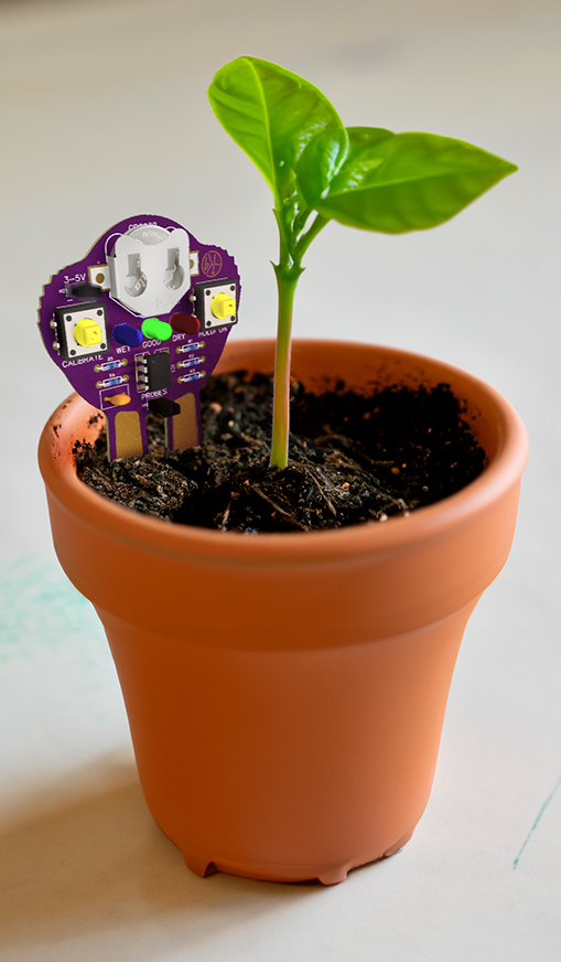 Shown above is a use case. The ears are the probes! Just drive them into the soil and follow the calibration procedure [below on this page.] If you're using my PCB template, you may notice the 'fuzz' on the bunny's cheeks which serve as grips. The Bun-Bun moisture sensor can be calibrated once for your project or garden setup and when you need to test, re-insert the ears (generally in the same spot and away from the plant's roots) and hold the power button for the result shown on one of three LED's. Then remove the device and clean it off with a damp cloth. Since the calibration is pre-set, you can keep the sensor nice and dry when you have no need to test and the battery will last for years. Just keep the main part of the PCB, the face, above the soil or water level as that may damage the circuit or battery. . 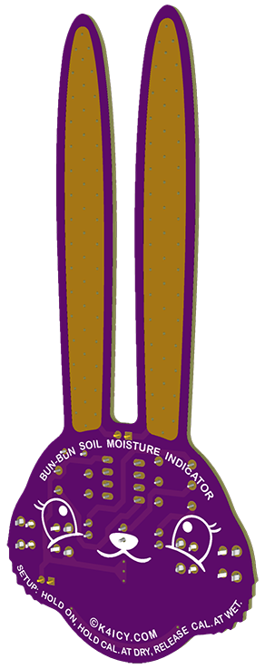 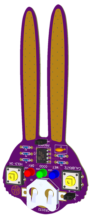 Look at how CUTE this PCB is!!! Gerber files are posted below if you wish to send off the make some for yourself and you'll also find program sketches for both the ATTiny85 and Arduino setups [below]. Keep in mind that you should be comfortable with programming ATTiny85's before ordering this board from a PCB fab such as PCBWay, JLCPCB, OSHPark or etc.. I have a general programming tutorial here. [Still a work in progress, but YouTube has many videos on the subject.] YOU have my permission (without having to ask me) to MAKE and SELL the Bun-Bun using my provided Gerber files, under the Open Source use license as long as "(c)K4ICY.com" or some credit to me is given, if using the same physical design. If the circuit and sketch are close enough and the shape of the PCB represents some kind of animal face with probes as some part of it, please consider a small note of credit as well. Design is OPEN SOURCE: Creative Commons - Attribution-NonCommercial-ShareAlike 3.0 - CC BY-NC-SA 3.0 Feel free to augment the sketch and/or the circuit, as well as redesigning the bunny face as this should provide more fun to youngsters in their scientific endeavors, whether exploring botany or electronics. . . How Bun-Bun was born: Not long ago, my niece (through my sister) had to come up with a science fair project. I had the idea that she should grow plants and use an Arduino to help the watering process. My sister ordered in an Elegoo Arduino Starter Kit and brought that, her laptop and a really dry and neglected house plant over to my house where we would eventually come up with an Arduino sketch which could measure the moisture content in the plant's soil. My sister was fairly interested in the whole process but I can't say as much about my niece (because she's a teenager.) We were using the Serial Monitor on the laptop PC to show us the relative values sampled and we had to calibrate the probe's effective measurement range by writing down the numbers and manually changing the variable presets in the sketch and re-uploading to the Arduino each time. This was tedious but became more interesting when I added LED's. . . I envisioned a solution in which a one-button calibration process could be made and stored on a portable unit, without the need for the PC or Arduino dev board. I then imagined a cute solution for the design of such a product, and what better aesthetic for the probes than bunny ears! I was able to send the updated program sketch to my sister, but I believe that they decided not to use it as most of the time in the experiment was run using the initial sketch and it's dynamics. . . But none the less, within no time they had an array of lima bean plants set to grow, one set, given water according to a recommended schedule, and the other, given water ONLY when the Arduino sketch said that the soil was ready. The plants made it to the science fair somewhat intact from the ravages of feline curiosity and my niece got an A+ in a well-executed display showing the joint application of agriculture and engineering! . . Shown below is the key for each LED indicator as setup on the Bun-Bun PCB. A Red light means that either the sample medium, such as soil or water is past the 'dry' threshold or the probes are not seated within the medium. A Blue light indicated that the medium is too saturated with water, or the water level in a level test is too high. Too much water can harm the plant. A Green light means that the moisture test indicates optimal conditions for your plant, or in a level test, everything is within range. When in the process of calibration, if the LED's blink rapidly in succession, then there is an error in that process. . . A major inconvenience soon became a major issue as my sister and her daughter had to constantly re-take reference measurements of both dry soil samples and wet nearly every time they checked on the plants, updating these recorded ADC readings in the sketch and having to re-upload the sketch each time to their Arduino. And I won't even begin to talk about the avid "scientific" interest from their house cats! This added another variable for sure, but you never want to vary your testing thresholds in the middle of an experiment. There are always variations to consider within an experiment setup, taking less-controllable factors into consideration, including the soil compositions between each plant subject, the temperature and yes, the small amount of oxidation on the sensor probes which increases over time. These factors can degrade the accuracy of the observations. We can't easily fix those issues, but we can make the process of re-adjusting for those variations a feature of the product. The Bun-Bun circuit and associated program sketch makes it easy to reset the test range: The power button has to be held down through this process of course, but all you have to do is first, place the bunny ears probes into dry soil and press+hold the Calibration button. Watch out for the roots! So, just maintain a space in your flower pot where the ear probes usually go. The red LED will rapidly flash telling you that the ADC value for the dry test condition has been taken and this will set the boundary ADC reading edge for the driest possible calibration. The green LED now blinks (more slowly) letting you know to prepare your wet/saturated soil condition. Keep the Calibration button held of course, but now fill your flower pot to the limit of where it can't accept any water. If this step will cause harm to the plant, you should do this in sample pot without a plant. You'll have to wait and add more water in a few cycles due to how long it takes to saturate thoroughly through the soil medium. Once the soil is wetter that it should be, release the Calibration button before removing the probes and the blue LED should now rapidly blink for a bit. The wet end of the ADC range was also recorded and these two numbers will then be written to the ATTiny85's on-board EEPROM memory. If all goes well, the Bun-Bun will likely go to the 'wet' indication with the blue LED in a solid state until you remove the probes. The possible test range should now be established and the the states of the three LED's, (Too Dry = Red, Good = Green and Too Wet = Blue) now have thresholds determined by the range gap factor. When you do remove the probes you should see the green LED light during the transition, and once the probes are clear, the red LED should be lit. If not, there's likely a calibration error by which, you should clean the probe surface off with rubbing alcohol and retry the procedure. IF THERE IS AN ERROR INDICATION (all LEDs blinking in Cylon stlye succession,) three things are likely: 1) The ADC readings were within 50 bit levels (0 - 1023,) meaning that the conductance or resistance through the medium is simple too narrow between each state. This can be due to several factors including the state of the probe surfaces or the resistor used to bias the sensor network (R4). The readings may have been take out of order, as in the 'wet' reading was taken in a drier state than the initial reading, or maybe the soil type is super conductive, like loaded with some mineral and water adds very little in the way of conductance. If something is broken in the sensor circuit, use a multimeter to test between each probe, and between each probe and both GND and VCC. There should be no continuity between the probes and only one of the probes should be connected to VCC, with the other reading the resistance of the bias resistor. 2) The Calibration button was subject to contact bouncing or the button was released before both test extremes were measured. Try calibrating again, starting from a sure dry medium state and make sure the button is held until the probes are subject to the wet/saturated condition. 3) The EEPROM was not written to correctly. This should be a rare problem but one of two things could have happened: the most likely is that there isn't enough power being provided to the ATTiny85 IC, so check the coin battery or power source. 2v is the minimal before things go haywire. Unlikely, but possible, is that the EEPROM has been written to too many times. You would have to calibrate 100,000 times at least for this to be true, but you could up the address numbers to a new position. . . The Bun-Bun is an excellent soil moisture indicator, but it also makes a great water level indicator! If the level is small enough to immerse the ears, the unit is perfect as-is, but keep in mind you DO NOT LEAVE BUB-BUN SUBMERSED in liquid for any length of time beyond taking a measurement as the PCB is not designed to protect from leaching, corrosion and other inclement factors. A probe extension header has been provided on the PCB which will allow you to use the the Bun-Bun for extended periods of time for both soil moisture and water level indications. A permanent-state switch can be used to keep the Bun-Bun on if using and external power supply (provided through the other set of header pins) and a proper corrosion-proof probe set can be ran from where the Bun-Bun unit is kept dry, to the test medium. To set up external probes for water-level indication, you could cut two lengths of corrosion-resistant wires or rods and affix them to the depth of your water vessel, or any particular non-metallic container intended to hold any conductive non-flammable liquid, spacing them no more than an inch or two apart, and calibrate first in the 'dry' condition with liquid making minimal contact with the bottoms of the probes and then in 'wet' with a full container. Do not make the first reading with no contact to liquid, otherwise the ADC will read just 0. Spacing between the wires may be critical and parametric to the length of the test probes and an different value of resistor may be used. Did you know that a set of moisture sensor probes can be used to read the conductance of human skin? Simply change (R4) to 1 meg ohms in value and use Bun-Bun as a neat "mood detector" gadget to play tricks on your friends! . . Circuit Description: Most of the circuit action happens within the ATTiny85 microcontroller, but a few extra components are required for the "eyes and the ears" of the Bun-Bun device. The symbol B1 [below] looks complicated, but the part is just a piece of stamped metal, when soldered to the PCB pads, forms a battery holder clip for a '2032' lithium coin cell battery, the same kind in most car key fobs. If building from a kit, soldering the clip may be the most difficult part as you need to gently hold it in place while soldering each tab. It takes a bit of heat and time due to the size. This circuit can run from a 2.5 volts to 5.5 volts power supply, so you could use 2 or 3 AAA batteries as well if you have a battery case instead. Or, you can also power the circuit from a USB 5 volt source, or even a USB portable battery charger. SW1 and SW2 are push button switches and the bog-standard 12mm kind with the attachable button caps which are found all over Amazon and like sites are recommended as the small rubberized tactile buttons may not pass enough current to run the circuit. SW1 temporarily supplies power to the entire circuit, but you can certainly use a small toggle switch. SW2 is used for the calibration process and is connected to PB3 (Pin 2) of the ATTiny85. An internal 'pullup' resistor is used on the Tiny for create a default 'high' logic state on that pin, and the switch causes that input to see a 'low' logic state. C1 across SW2 helps to reduce switch bounce. Switch bounce are very quick connect/disconnect states that can occur during the instant the switches metal surfaces are trying to make contact. These pulse states can make the very fast microcontroller believe the user is pressing the button multiple times, so it is good practice to use a capacitor to smooth the pulses as well as software implementations. LED's 1 through 3 are the indicators which are powered by ATTiny85 pins PB2 (Pin 7), PB1 (Pin 6) and PB0 (Pin 5) through current limiting resistors R1, R2 and R3 respectively. If not building this on the bunny face shaped PCB, you could certainly use an RGB common cathode LED. R4 is part of the resistor network pad that is formed by, both it and the bunny ear probes (within the soil or liquid medium.) The voltage/current provided by the battery (~3v typ.) is divided by this network and read by the ATTiny85's ADC (Analog to Digital Converter) via A2 (PB4) (Pin 3). R5 is simply a 'pullup' resistor on the Reset pin (PB5) (Pin1) as it shouldn't be left 'floating' which may cause an accidental Reset. Header pins H1 is available as a place to connect external probes as mentioned above and H2 provide a convenient place to wire up a power source besides the 2032 coin cell. If using a bunny head PCB kit, remember to remove the coin battery before connecting to another power source. If building this circuit using an Arduino Uno, wire up the connections to the board using the assignments set in the fist part of the program sketch for the Arduino. . Scematic for ATTiny85 Version - Click for Printable PDF .CLICK HERE TO DOWNLOAD THE READY GERBER FILE FOR FAB AT JLCPCB OR PCBWAY CLICK HERE TO DOWNLOAD THE .INO FILE for the ATTiny85 SETUP CLICK HERE TO DOWNLOAD THE .INO FILE for the ARDUINO SETUP . Here's a layered view of the PCB layout: . . Shown here is my solderless breadboad setup prior to designing the PCB. For the test probes I used a screwdriver handle to two sets of tweezers affixed to it with electrical tape. It was just a quick solution using things I had on the work bench. As shown, the test probes are lowered into a cup of tap water where I was able to test the calibration process. Shown on the middle right is an Arduino Uno with a custom ATTiny programming 'shield' connected. . . Here's a breakdown of the sketch: . Install library for use of the EEPROM and establish the pin assignments... [On the ATTiny85] - - - Note the Pin Assignment Numbers for Hookup - - -
[On the Arduino Uno R3] - - - Note the Pin Assignment Numbers for Hookup - - -
Global variables...
Setup...
Read sensor...
User initiated calibration process...
Here's a typical setup for using the Bun-Bun soil moisture sensor. One half of the planters were given water on a schedule regardless of soil condition and the remaining planters were given were only given water when the moisture sensor and associated sketch determined that the soil had passed its predetermined threshold for low moisture content. The science fair project focused on finding the balance between water conservation and optimal plant water delivery. . . When technology is used in a beneficial manner such as in the assistance of smart agriculture, the world is better off. Projects like this can teach today's youth to be better stewards of the Earth when they are adults. The Arduino is a great platform for bringing higher technology to the masses, democratizing the creation of solutions for tomorrow's problems. .  There's more to follow including easy and concise instructions for loading the sketch on to an ATTiny85 IC as well as building guidance for the Bun-Bub device and suggested use setup details. Instructions are also planned for a kit version of the Bun-Bun if you wish to produce those. . . Contact me at mikek4icy@gmail.com 73 DE MIKE K4ICY Updated 12/12/23
|
||||||||||||||||||
