 Arduino Projects By Mike, K4ICY Arduino Projects By Mike, K4ICY
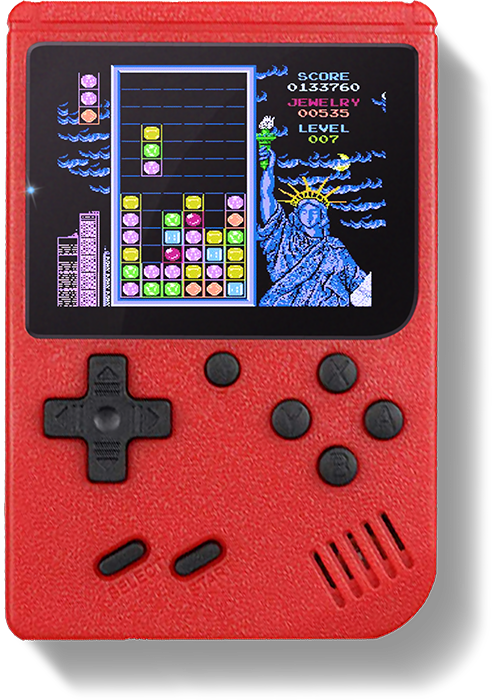
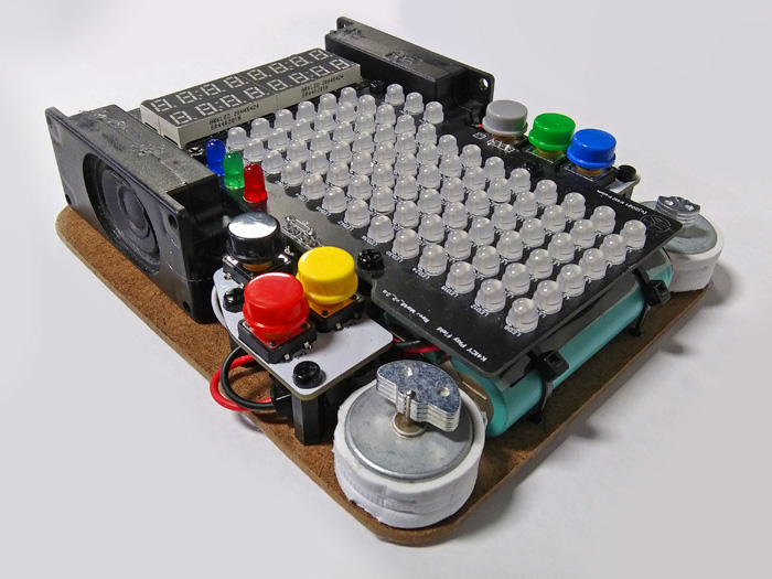
 Weekend Radio Click Here for More Electronics Projects and Tutorials By Mike Maynard, K4ICY _ Columns for Arduino by K4ICY A Fan-Built Retro-Inspired Handheld Puzzle Game based on Sega(R) Columns _ 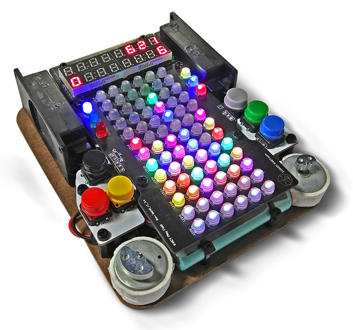 The K4ICY Columns for Arduino Prototype Board Mark II - Revised March 2022 . "Columns for Arduino" is a homebrew portable handheld stacking puzzle game based loosely on the 1989 Sega(R) Columns arcade and console game, which was itself a response by Sega to the success of Tetris. This build is a more modern take on a plausible electronic device as would have been envisioned in the late 1980's before the advent of raster-based handheld platforms. The play is smooth and potentially fast-paced, visually appealing and enjoyable to the ears. Haptic response only adds to the experience. K4ICY's Columns for Arduino, with the ubiquitous and popular Arduino Uno (or Nano) at its heart, using the ATMEGA328P microcontroller IC, uses a 6 x 13 matrix of addressable RGB LEDs, two 8-character 7-segment LED numerical displays and a few other bells and whistles including portable Li-ion power, stereo music and sound effects and even rumble motors! This project should be easy to replicate by any intermediate Arduino builder, but plans and files for a more complex professional version are available for the experienced maker. I'm available to answer basic question but have very little time to assist with quagmires that are not on my end. Enjoy this journal page at least, but please do share with me your Columns build successes! .
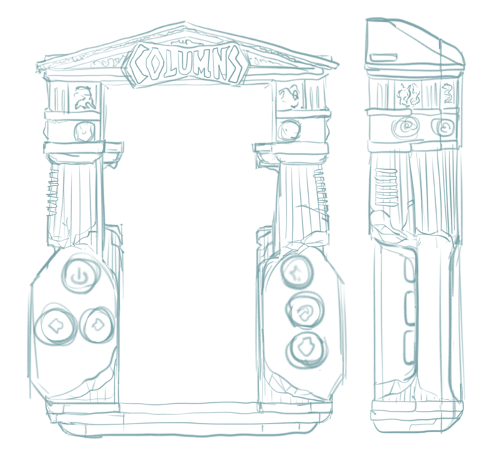
. GET THE ARDUINO SKETCH! [BELOW] . UPDATES: • February '21 - Sketch updated adding a second game: FLASH COLUMNS. New Splash Screen Menu. • March '21 - Nearly 100 Background Songs in place. • September '21 - Professional BMS (Li-Ion Battery Management Board) produced by JLCPCB • October '21 - More compact Numerical Display board produced (Compatible with MAX7219 boards) • November '21 - Professional Main Board with ATMega328P-AU uC IC produced by JLCPCB • December '21 - New Play Field Display Board using WS2811 5mm LED's as envisioned. • January '22 - Sketch updated including major optimizations. • February '22 - A third and fourth game added: TIME TRIAL and CRUSH COLUMNS! Audio track system overhauled - 255 Tracker/ChipTune songs added for fun. _ 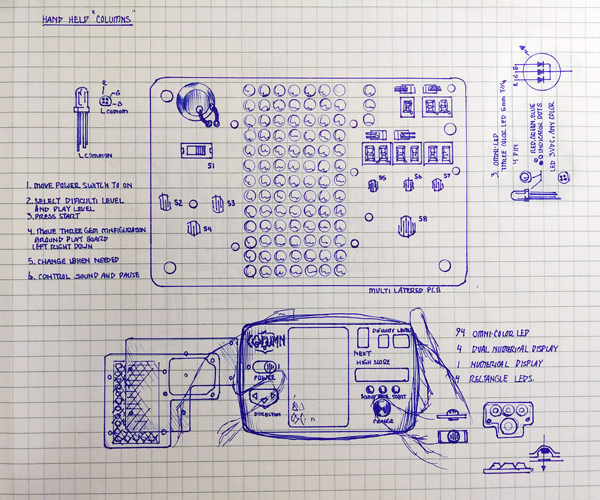 This concept sketch was drawn up back in 1992. The RGB LED then was not yet invented, but I dream of it! _ Way back when... Following the fame of Tetris in the late 80's and early 90's, Sega(R)'s Columns, was a popular stacking puzzle game in its own right which was available on home consoles as well as in the arcades. And just like Tetris, Columns still enjoys a steady stream of re-releases and updates. Back in '92, I envisioned a handheld version of Columns along the vein of the Coleco games from the 70's and 80's. I was introduced to Columns on the Sega Genesis console and was hooked for a bit. Yes, a version came bundled with the Sega Game Gear portable system released just a year prior, but there were a obstacles in owning and enjoying one for myself, not least of all was the cost as I was making close to minimum-wage then. The Game Gear had a $150-$200 price tag, ($330-$440 today!) It also ate expensive disposable batteries and had a tiny screen. I wanted that nostalgic feel and playability of a typical handheld game from my kid years in the 70's and 80's which often came with beady red LEDs or bright and colorful VFDs screens. On the flip-side, I wasn't too fond of LCD-based games. I felt that the austere binary black and yellowy-greenish-gray screens found in the likes of the Nintendo Game & Watch, Game Boy and others couldn't convey the bright and fantastic electric rainbow of fun which should be part and parcel to a game based on gemstone avarice. The buzzy and chirpy Piezo speaker sounds were fine, but sound effects and music would be nicer. On my concept, I even imagined using an array of some kind of faceted clear plastic lens to make that tangible 3-D 'bejeweled' look. One of the many barriers to realizing my design was that the awesomeness of the RGB LED hadn't even been invented yet! I considered the use of the, then available red/green (and pseudo-yellow) variety but with the rainbow of colors required to represent at least six different jewels, those would not work of course. In the game of Columns, a three-jewel arrangement (mathematically) poses no challenge to the player. Indeed, blue LED's as we know them today, (thanks to the diligent inventiveness of Shuji Nakamura who rivals the likes of Tesla and Edison, [Please check out Veritasium's video HERE,]) were not quite on the scene then, and the pseudo-blue LED predecessors only on shelves for a year or two were not yet capable of the vivid brightness and didn't come with the low price point we take for granted today. Those of us back then, who you could call "proto-Makers," used to covet those early blue-ish offerings and their prices matched their rarity. As you can see in the drawing, I would have been quite happy getting a hold of a full-color LED that was still future-tech. Perhaps, I could have used clusters of LED's and even considered multi-segmented numerical displays to represent each jewel as a shape, but the sizing and wiring complexity of such an arrangement would have made the game too large and cumbersome. Back-lit inversed LCD with color tinting and VFD solutions would have been an acceptable substitute except that they were not realistically available to hobbyists, just as they still aren't today. And for another barrier, there was the "elephant in the room," in that I had no adequate knowledge on how to design and build the electronics for such a device which was surely relegated to that of an electrical engineer with corporate resources, so this project was probably not a possible feat for the common homebrewer of the day. Consequently, I worked for an electronics contract manufacturer at the time and it amazed me so as to how our staff engineers could program and pack a sea of PIC and PAL devices on the many high-value PC boards we produced. I did manage to code a rudimentary version of Columns in MS QuickBasic 4.5 on my 286 PC and a little of that knowledge has come in handy with this project. In the span of one's life, many things shall come to pass, and many inventions of the heart will become manifest. Some 27 years later I was formally introduced to the world of Arduino development boards, AVRs and microcontrollers. To my benefit, I was practically weened on electronics by my late father, a television repairman, who was a great tutor. He fostered the love of coding with our early IBM 'clone' PCs, ZX-81's and TI-99/4a's. Later, Ham Radio would increase my fundamental electronics knowledge, but once I discovered that a non-engineer and hobbyist such as I could marry the disciplines of electronics and coding my mind began to race on the possibilities and I've formed a to-do list of awesome projects, many of which were strictly impossible way back when. My memory for building my own version of Columns was sparked back to life the instant I learned about addressable RGB LED's and OLED displays. My goal for this project wasn't so much a way to realize Columns in a retro handheld form factor but to teach myself more about microcontrollers and the devices that 'played' with them. I wanted to first limit this project to the simple ATmega328p (Arduino Uno, Nano, etc.) platform so that intermediate, and maybe newbies like myself could add something fantastic to their kit. I wanted to see how much I could stuff into this little AVR until it got upset... which happened more than a few times. I admit my sketch is poorly written by accepted programming standards, and it could surely use some streamlining from low-level C++ and assembly language, but I don't believe I'll ever correct a lifetime of bad (but adequately effective) coding. There are a lot of tweaks, shortcuts and problem solving involved that may make this sketch particularly hard to follow but maybe there are a few hidden gems for many Arduino enthusiasts to discover! . HOW
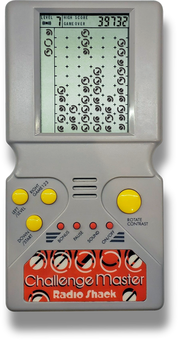
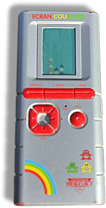
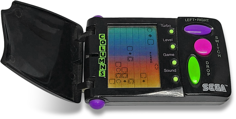
OTHERS STACK UP: While this project makes for an extremely playable, not to mention, fabulous Arduino project and clone of a popular puzzle game, I've just really reinvented the wheel. There have actually been a few commercial handheld offerings of "Columns" which have some commonalities. For sake of discussion we'll exclude the officially licensed video game ports which were offered on the Sega Game Gear and now later, on modern Nintendo devices including the DS and Switch as well as the Steam platform. Those are more or less raster-based video game ports whose host devices are more complex microcomputers. Offerings from Radio Shack and a few other Japanese companies used a monochrome 'character'-based LCD display and ran from a microcontrollers or very basic microprocessor whose silicon wafers were literally wired to the PCB and entombed in a "glop-top" dab of black epoxy resin. The movement of their falling gems or game pieces are in discrete steps, like my build, and their game dynamics are simplified.
Radio
Shack produced an excellent knock-off in 1992 called Challenge
Master (RS Cat. No. 60-2451.) This was one of two games
manufactured in the same form
factor, the other being a Tetris clone that went by the name
Stack
Challenge. I owned a Challenge Master that I bought in the
mid-90's and was excited to play it!
So, funny thing, even through two years of developing my
Columns
game, I
had completely forgotten about it until April of '21.
I
looked
all over the house for it but must have thrown it out a decade ago.
eBay had one for $7 with no cost for shipping, so I thought
it
would be appropriate to reclaim one considering this project.
Its
batteries leaked years ago which cleaned up with no problem and the
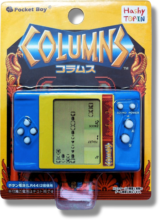
case and screen were in excellent condition. Despite the bleak coloration, there's something about those circular shapes and the rounded edges of Challenge Master's impressively durable plastic construction that gives it a certain friendly character. It's play field grid is 6 by 11 and uses a four-element character configuration to make 6 total unique game pieces, which of course is the same number of individual characters the Columns game uses. A seventh character made from all four elements active acts as the 'Magic Jewels' piece to save the day. It appears even on level 1, preceded by the "Charge!" trumpet jingle. There are only 9 levels of game play, but it may still continue play after that, for all I know, and levels can be chosen prior to start which give you a subsequent speed and score increase. Stack Challenge came bundled with two versions of what they call Tic-Tac-Toe, which send down game pieces in an 'L' arrangement which can be rotated like in Tertis, breaking up as is lands on different column heights. You can still find these handhelds on eBay as they were more-or-less generic - and from Radio Shack, which is not a bad thing, but yeah... not "Columns", so, of course many handheld enthusiasts don't find this very collectible. There were a few official (and unofficial) "Columns" handheld game devices over the years including a Tiger (US-marketed) offering, two from Japan and even an odd 'Euro' one. An outfit called Hashy Top-In produced a line of at least three "arcade" game handhelds under the brand "Pocket Boy." This version, which was a in diminutive horizontal form factor, was produced in the late 2000's and came licensed under the Sega Columns banner. It sported the official Columns play field grid dimensions of 6 by 13 and six individual configurations from three element-character whose shapes were reminiscent of gem stones. Game play is said to be basically "Columns."
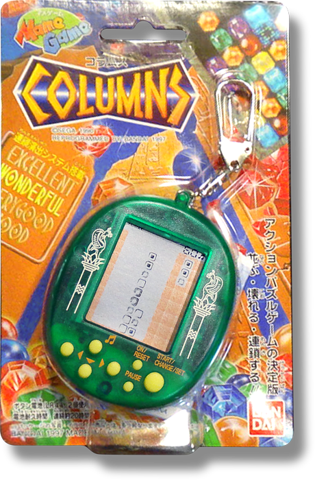
A Japanese offering (manufactured in 1997, selling
as late as
2014) from BANDAI came in a cute keychain form factor. There
were
several other offerings in this line which used the same design
including game titles like Bomberman, Galaxian, Space
Invaders, Pac-Junior and Crazy Climber. I couldn't find any
in my searching but these may actually still
be available for sale from a few niche Japanese resellers (in Japanese)
and were sold under the branding "Mame Game," which for those
in the emulator community is a curious choice of naming as "Arcade
Classics" would have had a less "I bootlegged it" stigma attached,
especially as an 'officially licensed' Sega product. [I digress.]
This
version is very tiny, like "Tamagotchi" small, and only sports a 6 by
10
play field and has only four square-shaped jewel combinations,
(though with three LCD character elements, six, is probably correct.)
Game play is said to be slow and choppy as tiny LCD games
are.
But still, how could any handheld enthusiast turn down
Columns on
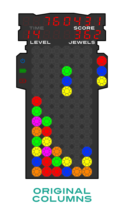
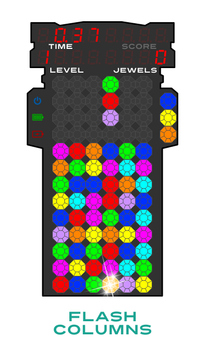
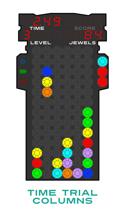
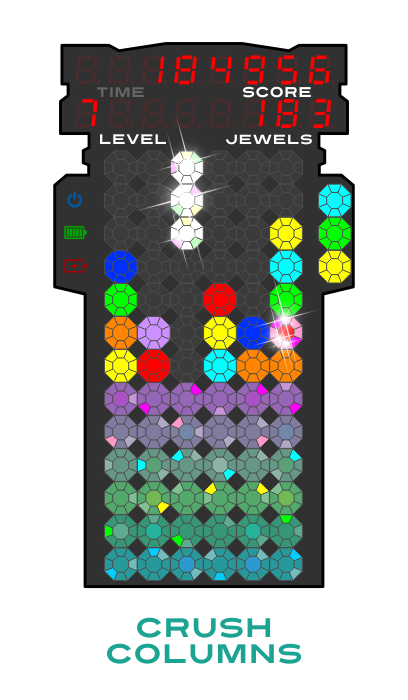
a keychain? _ 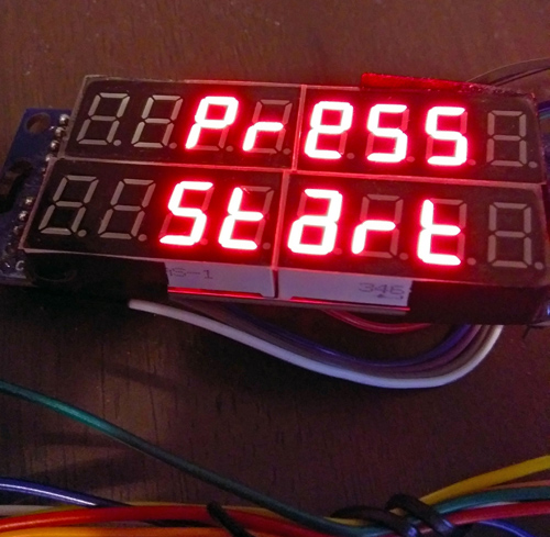 _ OPERATION: Power must be provided from a 5 volt source that can handle at least 1,500 ma! Options for power include; Direct "Wall-Wort" Charger Source, Phone Charger Power Bank (2Amp), BMS circuit provided here using at least 2-parallel 18650 Lithium-Ion cells, or use applicable power source. DO NOT operate from USB source! If using provided BMS design, tap the ON/OFF button to provide power. A Splash message: "Columns by K4ICY" will show on the Numerical Display accompanied by a sound effect, a short rumble from the motors and then a happy Columns tune should play while sparkly jewels will randomly appear on the Play Field. The game will now enter the Menu... There are 6 Control Buttons: [ON/OFF] located at the top on the left-hand side - The Power Button [START] located at the top on the right-hand side - Game Start / Play Piece Slow Down [LEFT] & [RIGHT] located on left-hand side - Lateral Play Piece movement / Game Select / Brightness Control [ARRANGE] & [DROP] located on right-hand side - Play Piece order and descent speed increase / Volume Control / Rumble Motor option. Auto-Shut-Off - The game system BMS will power down after 1 minute of no user input within the Menu mode. 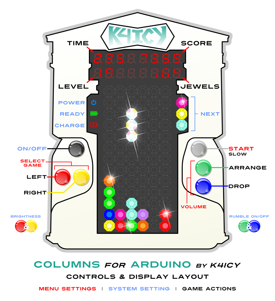 MENU: In the Menu mode, the HIGH SCORE, BEST TIME, the Current Score or Current Time from the last game and PRESS START message will cycle through the numerical displays. "Recharge Battery!" may show if using an applicable Li-Ion BMS and depending on the battery's charge state. Pressing the [LEFT] or [RIGHT] buttons will give the player the options to play one of four games "Original Columns", "Flash Columns", "Time Trial" and "Crush Columns." Pressing the [ARRANGE] (Up) and [DROP] (Down) buttons will increase or decrease the audio Volume Level which will not be permanently set in the game's microcontroller flash until a game has been started. There are 30 levels. Pressing both the [LEFT] + [RIGHT] buttons at the same time will cycle through illumination Brightness levels for the Numerical and Addressable LED displays. There are 16 levels, cycling through dimmest to brightest. Pressing both the [ARRANGE] + [DROP] buttons at the same time will enable or disable the haptic Rumble Motors, and its setting will not be saved until starting a game. Pressing [START] will
begin a new game, first
taking the player to a Pre-Game options menu: Pressing [START] again (or waiting 20 seconds with no user input) will continue on to the game... _
_
_
_
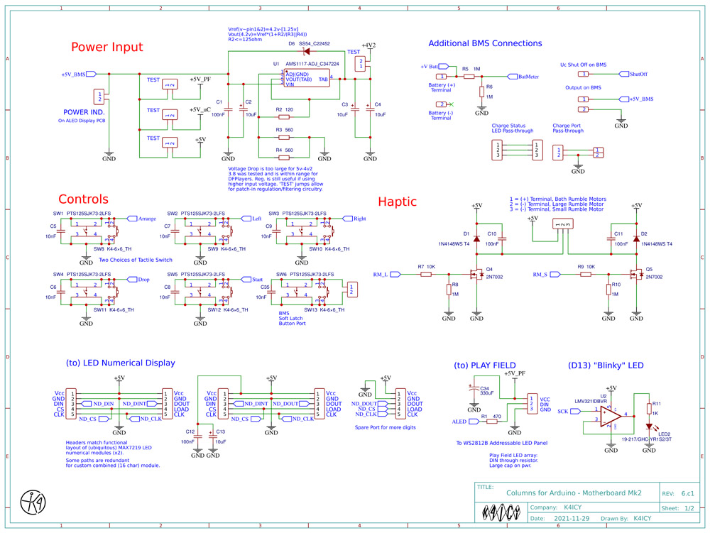
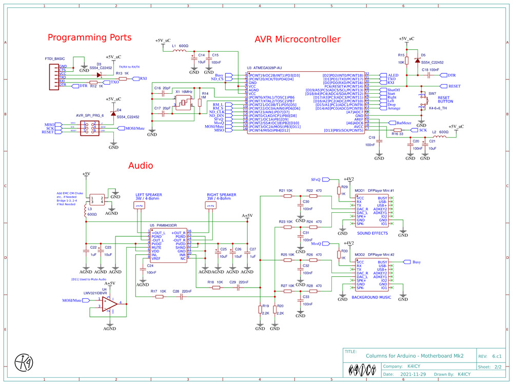
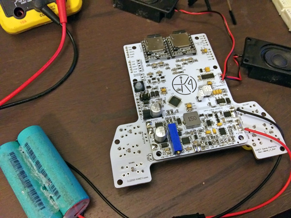
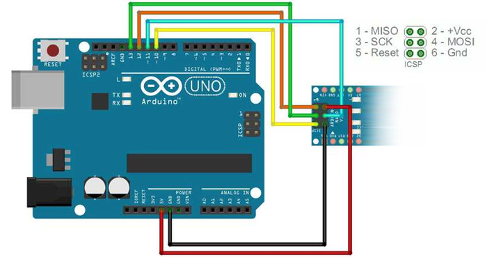
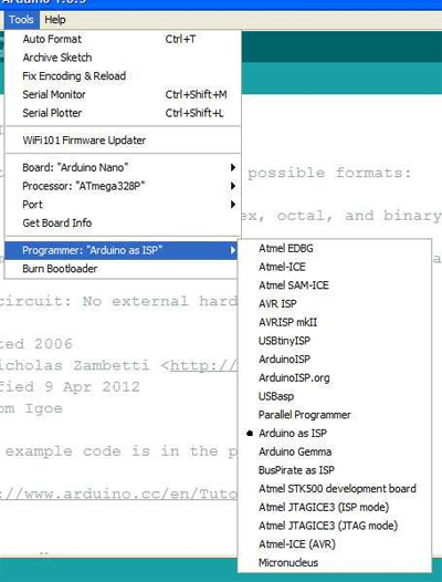
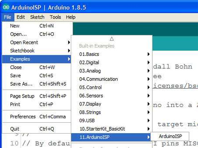
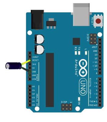
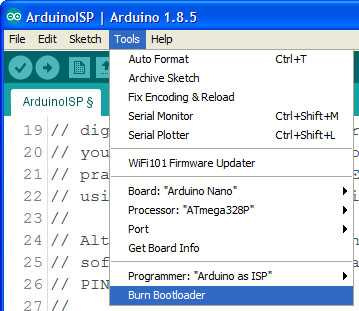
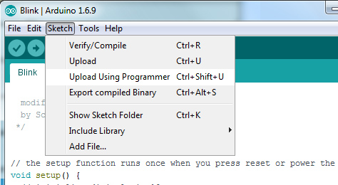
_ SOME PLAY MECHANICS: The Play Field grid is typically 16 high (xField) by 6 wide (yField) and the visible portion (xField - 3) is displayed on a matrix of addressable LED's. The top three rows are shrouded as part of the game play and some varieties of Column-like games treat the specifics of the top visible rows and game-over conditions differently. But unique to the K4ICY version, these rows can be thought of as a 'staging area' or 'soft zone'. The player can still position their Play Piece (unseen,) in this zone which can be used to the player's advantage, since a match may be found in a last ditch effort, but any jewels remaining in the 'soft zone' one the column settles will cause the game to end. The columns 'Play Pieces' march down the well (Play Field) by 'gravity', starting at 1 cell per second (at Level 1 / Difficulty 1,) accelerating a small amount as it progresses towards the floor. Game Levels are increased according to the number of jewels crushed, typically 25 each. A logistic decay curve is applied to the speed increase, per-level, which is increased by playing at a harder difficulty setting. In the K4ICY version of Columns, scoring is determined as follows: gameScore += (Jewels Smashed x ((Level + 1) x 10 x Number of Chain Reactions)) and additional points are given when the column is rapidly dropped downwards by the user: at gameScore += (((Cell Steps Down x 2) - 1) x (Level + 1)). Additional bonus points may be given for other factors including crushing matched groups of jewels exceeding 3 in number and for multiples of color types. Play Piece movement control is dependent on the Level/speed factor and the ability to aim is compelled to match the increased difficulty. This is a mechanism within the sketch that may need to be tweaked in the future as certain other factors can exacerbate unintended control awkwardness including button input debouncing (both electronic and coded) as well as game 'resolution', or the sketch cycling period and microcontroller computational speed. The Difficulty algorithm can be tweaked to bring the game into balance between play challenge and general play enjoyment. _ 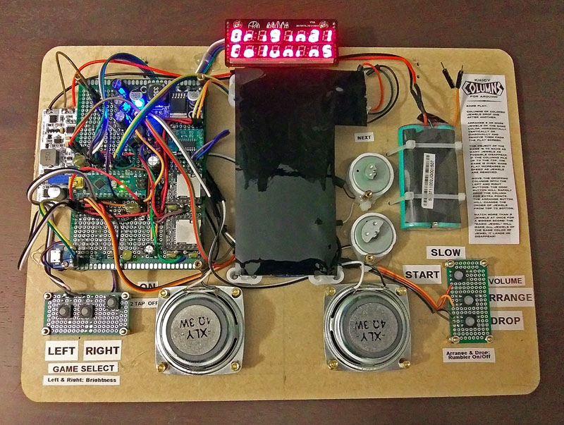 The K4ICY Columns for Arduino Prototype Board Mark I - Revised October 2021 Improvements included a custom SMD power/charging board and more compact LED numerical display. Includes newest code improvements. _ 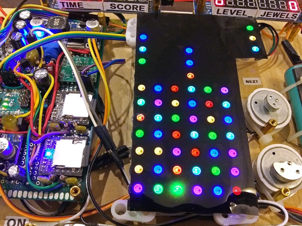 _ _ RESOURCE FILES: SCHEMATICS & SKETCHES There are TWO sequential build versions of Columns for Arduino by K4ICY: The MARK I and MARK II. The MARK I uses a standard Arduino Uno R3, Nano, or any other compatible board (SEE LAYOUT BELOW). The major components are easy to obtain and the additional support circuitry can be set up on a solderless proto/breadboard using DuPont jumpers. Main operational sections can be added in phases so troubleshooting is easier. The advantage of the Mark I is the ease of setup with (nearly) instant gratification of play. The above images show prior prototype versions which utilizes many precursory features that were later employed in the Mark II SMD PCB prototype, and this setup allowed for further development. A more simplified build is, of course possible. The current Mark I is represented in the virtual layout schematic (BELOW) and should be conpatible with the single sketch provided (barring any errors.) The MARK II requires custom PCB and SMD/SMT placement services from a company such as JLCPCB or PCBWay. The ATMEGA328P-AU microcontroller requires programming of the bootloader and sketch via an ISP programmer such as a separate Arduino Uno board (as ISP). The complex engineering logistics and troubleshooting requirements make this project suited for more advanced Arduino 'makers'. The advantage of the Mark II is portability and a long and fun service-life duration. The adavantage of the Mark I is ease in building. Libraries and sound files are required... YOU MAY DOWNLOAD ALL SKETCHES, LIBRARIES AND SOUNDS HERE: https://www.mediafire.com/folder/urk3xz7j6s90t/Columns Make sure to keep your AdBlocker on as MediaFire likes to bombard your browser with popups. [Sorry.] In the MediaFile folder, you'll find the necessary libraries, the most up-to-date sketch as well as the Sounds folder. The Sounds folder contains 13 files. 01.zip and 04.zip are regular zip files. 02 and 03 are multi-part zip files due to their unpacked size so use 7zip or your unpacking app to unpack a new folder from the ".001" file. You should have four folders: 01 - 04 containing .mp3 files, all named with 3-digit numbering. Once the sound files (mp3's) and unpacked on your PC, these folders can simply be copied to the root folder of your two required mini-SD cards. The total file size is around 2.2GB so the SD cards you use should be at least that, but not more than 32GB in capacity. Two identical cards will then be installed into the two DFPlayer Mini modules. The Columns sketch has been set up to run the DFPlayer track access in 0x0F mode which means the 'High' byte accesses any folder named 01 - 99 and the 'Low' byte access the folder's containing .mp3 files with any name between 001 - 255, with no need to worry about the order they were copied over to the SD cards. Please visit the DFRobot site and https://markus-wobisch.blogspot.com/2016/09/arduino-sounds-dfplayer.html for a lot more detail. For ease and convenience, I've basically duplicated the contents of each player's SD cards, and a little backup redundancy isn't a bad idea. I've organized each folder so that 01 has the sound effects, 02 has the Columns music, 03 has a lot of cool Amiga Tracker tunes, a.k.a. ChipTunes and Installer Music, and 04 has some Columns tunes that have been edited to make game play for Time Trial Columns a bit more more interesting. Since the tunes I provided are for only intended for your evaluation, If you wish to change the music or sound effects to something you own or desire to use, just copy over your files given the appropriate naming conventions for folder's 02 and 03. 01 and 04 will take a bit of research to replace, but regardless, you should study the sketch to see what sounds are accessed for what purpose. The Libraries required include: FastLED.h, LedControl.h and SendOnlySoftwareSerial.h and they should be first installed to you IDE - these are also in the provided MediaFire link. Please remember, as with any GitHub library ZIP file, don't forget to rename the unpacked folders without the text "-master" before installing them in your Arduino IDE. Any newer library revision later than April of 2020 hasn't been tested! If you have no issues running more current libraries, especially found through the Arduino IDE Library search dialog, that will be nice to know, but I was worried about trying to compile newer, potentially more-bloated code into the limited AVR flash space which was left. The DFPlayer Mini's require no library of their own as they are controlled in my setup, directly from the SendOnlySoftwareSerial library and byte-wise commands. _ Schematic for the Mark I Setup: Click to enlarge in browser... 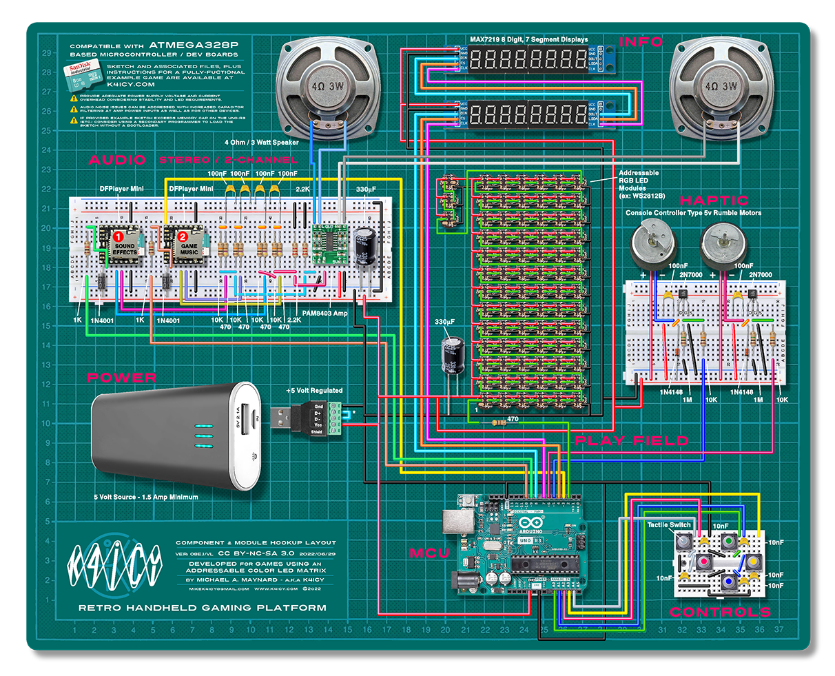 Direct download HERE... PLEASE NOTE! The most current sketch should fit and function on a standard Arduino UNO R3, but for Arduino Nano devices, you may need to either update either the bootloader or tweak a particular Boards configuration file in Arduino IDE as 1.5kb of space is essentially wasted when the Arduino developers omitted telling the IDE that the new Optiboot bootloader was smaller... no really! No need for anxiety - SEE the Video's BELOW and get back the memory space you already own and even upload at a faster speed! You may also choose to burn the sketch directly to your Arduino via the ICSP pins via a programmer, or another Arduino set as ISP, SEE BELOW which will erase the current bootloader as a directly loaded sketch will not require one. You'll have to remember to burn a fresh bootloader if you wish to use your Arduino for other sketches again. _ Current Prototype Sketch: FOR the MARK I (as shown in layout above) and the MARK II (manufactured version) - (Minor Expected Updates Planned...) columns_for_arduino_by_k4icy_ver08e1_02-27-22.ino _ Schematics for the Mark II Setup: Click to open PDF in a new tab, and to download... _ _ _ The above set of schematics detail the parts and connections for the Main Board PCB which includes the AVR microcontroller, audio amplifier IC and other required discrete components. Construction details are provided further down this page. And yes, I do plan on making the EasyEDA projects Shared and Open Source in due time. Here are the Gerbers, BOM and Pick-And-Place files for manufacturing: FOR the MARK II Main Board PCB Gerber_PCB_Columns_Mother_Board_Mk2_R1-6c1_2021-11-29.zip PickAndPlace_PCB_Columns_Mother_Board_Mk2_R1-6c1_2021-11-29.csv BOM_PCB_Columns_Mother_Board_Mk2_R1-6c1_2021-11-29.csv
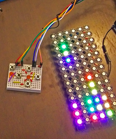
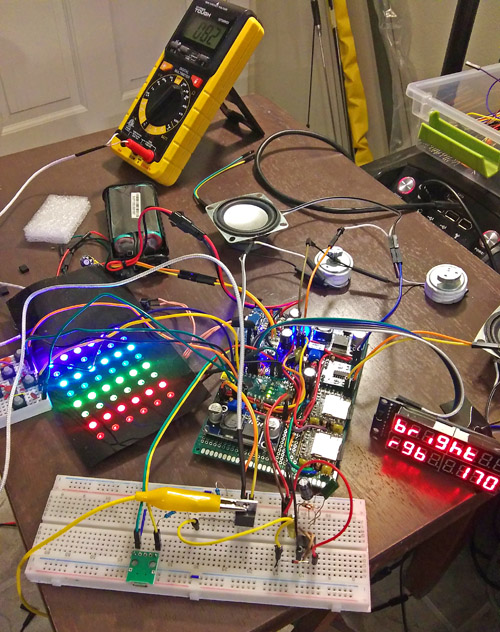
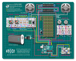
CLICK HERE to go to my Li-Ion Battery Management System Board Build Page. All associated manufacturing files will be found there. NOTE - The following PCB modules are completely compatible with an Arduino Mark I setup. _ _Schematic for the Mark II Compatible LED Numerical Display Daughter PCB: Click to open PDF in a new tab, and to download... SEE BELOW for a detailed description. _ 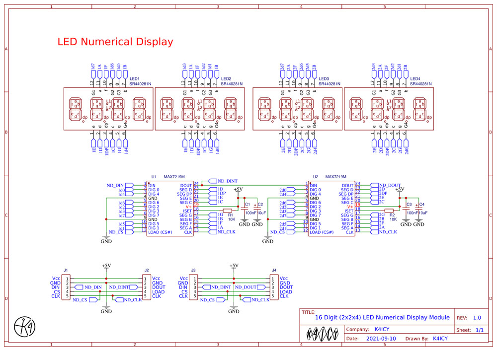 _ The above schematic is the textbook wiring format found on the MAX7219 data sheet. You may surely use the provided Gerbers and such as a study example, but if you wish to design your own, you'll have to take into account the particulars of the pin pitch, spacing and dimensions of your chosen LED digits module, and you'll likely have to design your own PCB layout. There are a vast variety of LED digit modules on the market, even for the required common-anode type, and of each type, quantities can be sporadic and few at that. I offer no guarantees here. Here are the Gerbers, BOM and Pick-And-Place files for manufacturing: FOR the LED Numerical Display PCB Schematic_Columns-LED-Numerical-Display-Module_2021-10-02.pdf BOM_PCB_Columns-LED-Numerical-Display-Module_2021-10-02.csv PickAndPlace_PCB_Columns-LED-Numerical-Display-Module_2021-10-02.csv Gerber_PCB_Columns-LED-Numerical-Display-Module_2021-10-02.zip _ Schematic for the Mark II Compatible Play Field Daughter PCB: Click to open PDF in a new tab, and to download... SEE BELOW for a detailed description. _ 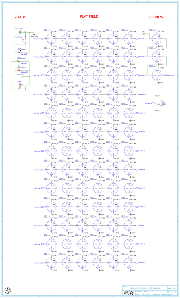 _ Since the WS2811 addressable LED's, which are the "F5" type are through-hole parts, if your PCB house doesn't have those in stock and can't solder those, you'll have to order in and solder those yourself. Each of 81 LED's, in total, have 4 fine-pitch pins! Here are the Gerbers, BOM and Pick-And-Place files for manufacturing: FOR the Addressable LED Play Field PCB Schematic_Play_Field_MarkII_2_2a_2021-12-01.pdf BOM_PCB_Play_Field_MarkII_2_2a_2021-12-01.csv PickAndPlace_PCB_Play_Field_MarkII_2_2a_2021-12-01.csv Gerber_PCB_Play_Field_MarkII_2_2a_2021-12-01.zip _ CONSTRUCTION: _ System Overview: The core of this game was first developed on an Arduino Uno R3 and later moved to an Arduino Nano. The 'star' of the show is the Play Field comprised of a grid of addressable RGB LED wafers (or 5mm F5 types). WS2811, WS2812 or any other models compatible with the FastLED library should work fine. I purchased sheets of 10 x 10 LED break-away wafer modules from Amazon, and soldered them together appropriately to form a 6 wide by 13 tall tiled grid. All that's required to run these LED's is an adequate power source - DO NOT power more than a few LED's using the Arduino board's power source!. You'll be required to source 5 volts at 1.5 amps (or more) with a large electrolytic capacitor bridging the connection close to the LED array for power smoothing. These LED's can be blindingly bright and consume upwards of 80 ma EACH, which add up! At full brightness, more than 3 amps are needed for my setup, however, because the sketch keeps them lit at a lower luminance, around half, the current consumption is around 300-600 ma total. The digital data input of the addressable LED comes from the Arduino through a 470 ohm resistor. This resistor is crucial as the tiny microprocessor embedded on each LED which can be damaged on current spikes. The resistor mitigates this possibility. The luminance can be user-set by pushing the [LEFT] and [RIGHT] buttons together during the main Menu mode, cycling through 16 levels. The game's info is provided via two 8-digit, 7-segment MAX7219-driven LED displays. This adds a real "old school" touch and allows for numbers to be displayed at any location, along with custom characters made via sending 8-bit binary (bytes) to the devices. The luminance is set along with the RGB LEDs as mentioned above. Sound is provided via two DFPlayer Mini Micro SD card MP3 Player modules. Each use an SD card (with no more than 32GB capacity) loaded with redundant copies of the MP3 audio files. One module handles Sound Effects and the other, Background Music. )))STEREO((( sound is fed through a basic mixing/filter circuit into a PAM8403 PWM amplifier feeding two 8 ohm 3 watt speakers via a "bridge" output. Most of the music files are natively in stereo and many of the sound effects have been edited to 'exist' in some portion of stereo space according to the sketch's determination. The stereo sound effects help to give the play a more immersive experience. Many Arduino experimenters have had issues even getting the DFPlayer Mini's to work, let alone play nice, but I found that sound files can be cued up nearly INSTANTLY using the SoftwareSerial command (native to Arduino IDE), or rather, Nick Gammon's SendOnlySoftwareSerial library functions and addressing the MP3 players directly. With this approach it is not readily possible to receive telemetry back from the players except from the player's 'BUSY' line. For more helpful information on using the DFPlayer Mini's, please visit: https://markus-wobisch.blogspot.com/2016/09/arduino-sounds-dfplayer.html There have been issues on my end with EMI noise in the audio thanks mostly to the MAX7219 LED drivers. Other sources, including buck and boost converters, will also contribute, but to mitigate EMI, first consider using short lead lengths, bulk capacitance on all power inputs and even inductors on the power feed for the final amp. The Mark I actually runs three switching power supplies and even the AVR and the cheap innards of the DFPlayers may also be contributors. The updated Battery Management System board should should help a bit. The powered speaker outputs of the DFPlayer Mini's are the PWM bridge types and are not generally good for mixing but the DAC outputs of the players work fine. Both SOUND and MUSIC volumes can be set together via the [ARRANGE] and [DROP] buttons in the main Menu mode. The builder can apply those to EEPROM memory if desired. Haptic Feedback is provided via two game controller rumble motors controlled by 2N7000 MOSFETS and other components. When the columns land, you sideswipe a wall or resting jewel, and especially as jewels are removed - YOU'LL FEEL IT! The option to allow for operation (or not) is made by pressing both the [ARRANGE] and [DROP] buttons together during the main Menu mode. Smaller motors, shakers or phone vibrators can be used. Also, consider placement of the motors near the button locations or where the palms of the user's hands will be. _ Considerations: Power is a hard beast to tame on the Mark I version. My earlier prototypes included a buck converter (down voltage), boost converter (up voltage), the hacked battery management system (BMS) controller board from a cellphone power bank (Li-Ion 1S/2P cells,) a circuit to cut off game operation on the connection of a charger source and on-delay circuit to keep the battery board from going into protection mode because of the initial voltage dip/current spike. A better solution has been made through the custom BMS for the Mark II but for the latest iteration of the Mark I, I feed the regulated 5 volts of a phone charging bank directly into the 5 volt line of the Arduino. This eliminates having to unnecessarily boost the voltage to over 7.5 volts only to have the Arduino's internal regulator reduce it back down along with a loss. Also in the mark I update, the DFMini Players are now supplied directly from the 5 volt rail through diodes which provide an amount of voltage drop. You should be considering device current consumption, voltages and power requirements. Building a game that is portable will benefit from the use of an adequate Li-Ion or Li-Po power source but that requires added BMS circuitry for safe use. Any type of power supply running 5V at, at LEAST 1.5 Amps is required. DO NOT power this from your PC's USB sockets. There is no actual need to use a buck converter for the DFPlayer Mini's (but I wanted to play with one anyways,) instead, an adjustable LDO linear regulator is fine to reduce the player's power voltage down to a specified level. Some builders have had no issues with using them at 5 volts, but it's not recommended. Most regulator require a good 1.5 volts of separation between the input and desired output (voltage drop) and going from 5.0 v to 4.2 v with these are not obviously possible, but in my trial, I was getting around 3.8 v. The Mini's can handle down to 3.0 v. The Arduino can run fine from the BMS's native 5 volt source by itself, but as power goes through the Arduino board's built-in voltage regulator, the AVR is actually receiving as low as 3.8 volts considering drop-out! It will still run, but performance may have issues. Running a 5 volt input source through a boost converter is suggested when using an Arduino board. In my tests, the appropriated Jackery BMS circuit had poor voltage regulation and the sudden powering of other current hungry devices would cause the Arduino to reset due to drop-outs. I found that I had fewer issues if I could get 7.5v to the Arduino for overhead so that it's own LDO regulator would produce a consistent 5 volts. When powering just a basic AVR directly with 5 volts, of course, a boost converter is unnecessary. _ 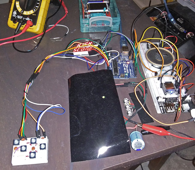 The original OG setup. Use a little solderless breadboard to make a controller. _ Basic Steps: Aside from keeping lead lengths short and organized... START OFF SIMPLE!! You can't really screw up your Arduino dev board if you aren't powering any of the outboard devices directly from it. Solder together a few rows of the addressable LED wafers (or NeoPixels) [AS SHOWN BELOW] according to my description, and don't forget the capacitor across the LED's main power leads as well as the resistor in-line on the data signal, and ensure that the LED's are powered by a reliable external power source that is NOT from the Arduino, running 5v with at least 1.5 amp handling capacity. Then you can try an easy 6 x 6 field, maybe starting off with cut lengths of LED strip tape. Change the Play Field dimension numbers in the sketch to: // Play Field const byte xField = 9; // Play field vertical dimension - Includes 3 'Soft Zone' rows above actual LED play field const byte xFieldLimit = (xField - 3) ; // Can't address LEDs that don't exist const byte yField = 6; // Play field horizontal dimension Once you wire up the Play Field the sketch should work fine without any of the other devices attached... at least I believe. You should now see some random glitter flashes appear. What could go wrong? If you get no LED's lit, check your connections then check the FastLED setup parameters as described below. Check for proper power input as well as for any wiring shorts. Start off with just one LED run directly from your Arduino with a FastLED example sketch. If the colors just seem off, check for the correct color order (i.e.: RGB, GRB, etc.) in the FastLED setup. The LED's supposed model number is not strictly indicative of what that part's manufacturer implemented. If your Play Field is only lighting up on some random portion of the bottom or all the LED's start glitching once a certain LED is lit, you may have a bad LED or you have a short or a cold contact. As I suggested, start off simple. 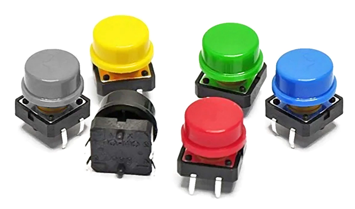 Now wire up the Buttons, each with a 10nF capacitor across their leads for help in debouncing. You should be able to play a basic game! Though, you'll be a bit blind, but press [START] a couple of times to move through the Menu which won't be visible until the numerical displays are attached. If you still see the 'glitter' effect on the Play Field then double-check your button wiring. Make sure their connected to GND and that the tactile switches are connected correctly, of course, using a multimeter is suggested. Once you're able to play a basic game with some buttons and a 6 x 6 Play Field, you can expand the addressable LED Play Field to what you like. I suggest the game standard of 6 wide x 13 high, but keep in mind that on an Arduino UNO or NANO, the memory for this sketch is pretty much stretched to the max and making a field larger than this may tax the AVR's SRAM management and erratic behavior may occur. 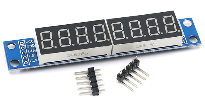 With a working Play Field and Buttons setup, try connecting the two LED Numerical Displays. They're cheap, by the way, and they're designed to daisy chain end-to-end, but like the Play Field LED's, the power should be run from a separate source than the Arduino. Also, on the MAX7219 LED display modules, the pin marked "LODA" is just the output of the first module which goes on to the "CS" of the second. Everything else is mostly self-explanatory. These displays are an Arduino maker's favorite and pretty hard to get wrong, so if these run you'll now have the scores and info. 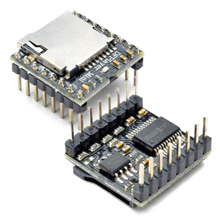 Adding the audio will be the hardest and trickiest part! The components should work if you build according to the schematics but assume that those cheap irritable little modules are going to be likely to throw you for a loop. Please refrain from messaging me with questions about the DFPlayer Mini's as I wouldn't know where to start and there are more apt experts on the subject, particularly the FDRobot site as well as other builders including Markus at: https://markus-wobisch.blogspot.com/2016/09/arduino-sounds-dfplayer.html. A lot of Arduino makers love these players and they're jellybean cheap. You may find that on sites like Amazon and eBay, there are many complaints about counterfeit and dead units. Since you can find these for around $6 a piece, order a couple from different vendors, or better yet, get the originals from DFRobot. Read more BELOW... 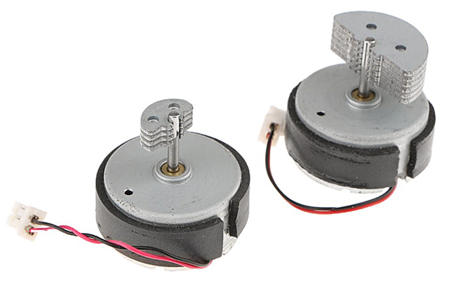 Why not then add those rumble motors? - Arduino 101. If you can't get them for less than a few buck on eBay, just find an old 360 game controller or a couple of outdated cell phones and purge the ones from those. The motors should be rated at 5v and won't actually draw too much current. If they are the 3.3v type, a simple resistor divider network will work. Try 1k ohms for the top value and 2.2k for the bottom. Try some of the tinier ones meant for smartphones for less rumble because the X-Box 360 type are really meant for sniping combatants not clinking around some gemstones. The tiny ones are easy to find on eBay and Amazon. Install them around where your hands will rest. _ More Detailed Description to Follow: _ 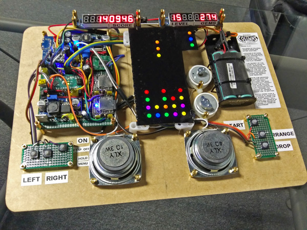 The K4ICY Columns for Arduino Prototype Board Mark I - Revised October 2021 _ My first prototype started off with this 10 x 10 module sheet of WS2812B addressable RGB LED SMDs (5050) from BTF-Lighting. The FastLED library sees them fine, but be sure to designate the part number type in the sketch command. You will also have to verify for the correct RBG data order. The procedure for determining that is simple and there's and example sketch for it. These SMD wafer modules are "WS2812B" and it's data order is 'GRB'. The 'B' in the part number denotes the black paint. FastLED.addLeds<WS2812B, DATA_PIN, GRB>(leds, NUM_LEDS); The stand-alone 5mm "hat" profile 4-lead LED's are "WS2811" and their data order is the more common 'RGB'. FastLED.addLeds<WS2811, DATA_PIN, RGB>(leds, NUM_LEDS); As for programming with the FastLED library, there's a lot of information out there and one great YouTube tutorial series to watch is at: https://www.youtube.com/c/ScottMarley FastLED Basics Tutorial Series IMPORTANT for GAME SETUP: _ _
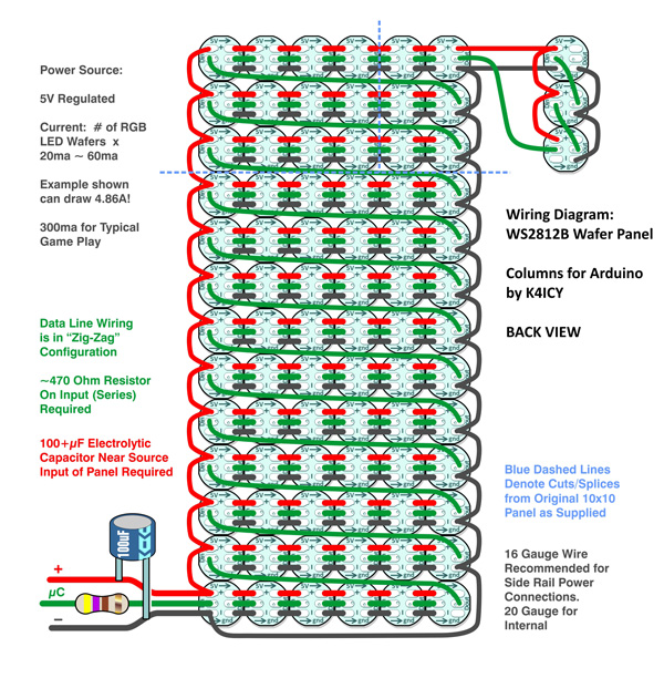
As
shown in the following wiring diagram, a 6 x 13 element panel can be
created by breaking down the provided panel to give you a 6 x 10
element section. The LED wafers should always be oriented in
the same
direction, which is obvious for easy wiring, but the viewing angle (and
color fringing effect) of RGB sub-elements will be controlled.
A 4 x 3 element section on top and
a 2
x 3 section to the side of that finishes out the 6 x 13 arrangement.
Stack three on top of each
other
for the preview column jewels. _ _ _ If you wish to go the snap-panel route, follow the diagram above. The green wire path shown, represents the data signal line from the Arduino. You must insert a resistor (330 to 1k ohm) in the data line or the first LED may fail. This is a documented issue noted by other builders. The data line is daisy-changed between each LED wafer [from D-Out to D-In] and my sketch, by default, requires a "Zig-Zag" wiring pattern from bottom-right to top left as viewed from the back of the panel. LED #1 will be the one on the bottom right when viewed from the front. "Serpentine" wiring or any other scheme can be used as well except you will have to alter the part of the sketch that assigns each LED a number to match each corresponding X-Y array position. The FastLED library also offers a convenient command to interpret different wiring schemes.
The +5 Volt and Ground
lines
should be distributed via 'rails' along the sides
to distribute the
current more evenly throughout the LED group as color changing due to
progressive voltage drop is
an issue on longer strings. Power and data are then linked
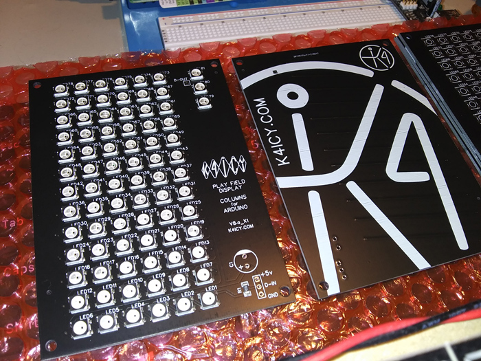
between all middle connections. First - Never power more than 3 addressable RGB LEDs directly from the Arduino's power supply pins! You will destroy your Arduino, or more likely, it's LDO voltage regulator. You must use a separate 5v power supply and in my setup, I use a 5v Li-Ion supply to power the display and a 'boost' converter to provide 7+v to the Arduino Uno or Nano board. Each addressable LED, in general (i.e.: WS2812B) will consume a minimal of 20ma each just for it's built-in microcontroller when all RGB elements are completely off. Each element, R,G & B, when powered to full brightness level can typically consume up to 60ma EACH which means the total current draw for EACH wafer can be as much as 200ma, which can add up when in numbers. Under test, using my constructed panel at full brightness I was drawing around 4.8 amps, and that is enough to easily set smaller bodge wires in a circuit on fire! Though LED's are generally considered to be cooler than their incandescent counterparts, enough heat can be produced to both start a fire and damage the LED's themselves if confined. _ _ Fortunately, at the default game setting for RGB LED Brightness of "170" (Game Menu Brightness of "7") and considering that the typical jewel play field will consist of LED's with more discrete values of specific jewel colors, and most likely not employing every LED wafer at once, my panel typically measured around 300ma of current consumption, 600ma at peaks. Take consideration of how you mount them in your project, as they can get really hot if enclosed between sheets of plastic and ran too brightly without some kind of cooling, as case in point, I melted a plastic tinting sheet which nearly fused to the LED wafers. WARNING: Upon starting up this sketch with an affixed LED panel such as this for the first time, in the main Menu, press both the [LEFT] and [RIGHT] buttons simultaneously which will cycle the Brightness of both Play Field and Numerical Display from dimmer to brighter within 16 steps that will cycle over. The builder can set this with the Play Field unplugged to be safe. Also use a wiring gauge thick enough to keep things safe and cool. 16 awg wire for the rails and 20 awg for the internals will work fine. The data line can be any small wire guage. _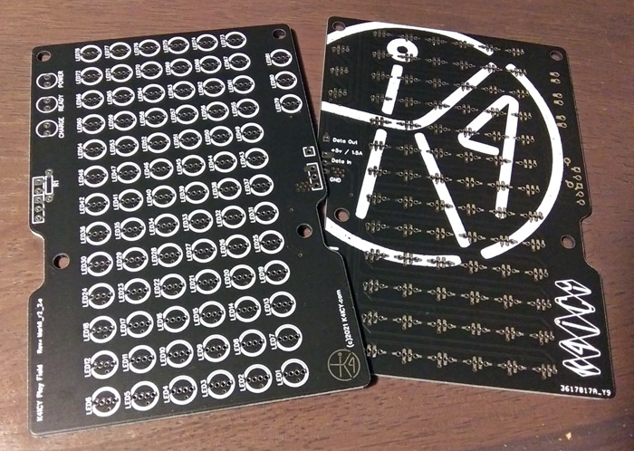 This is the 3rd incarnation of the Play Field and 2nd PCB version. 341 hand-soldered joints! _ 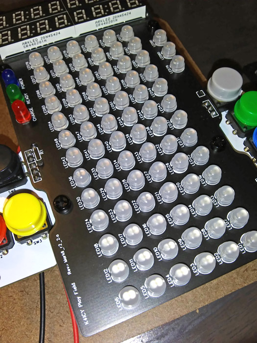 The installed Play Field, populated with 81 WS2811-F5 addressable LED's. _ 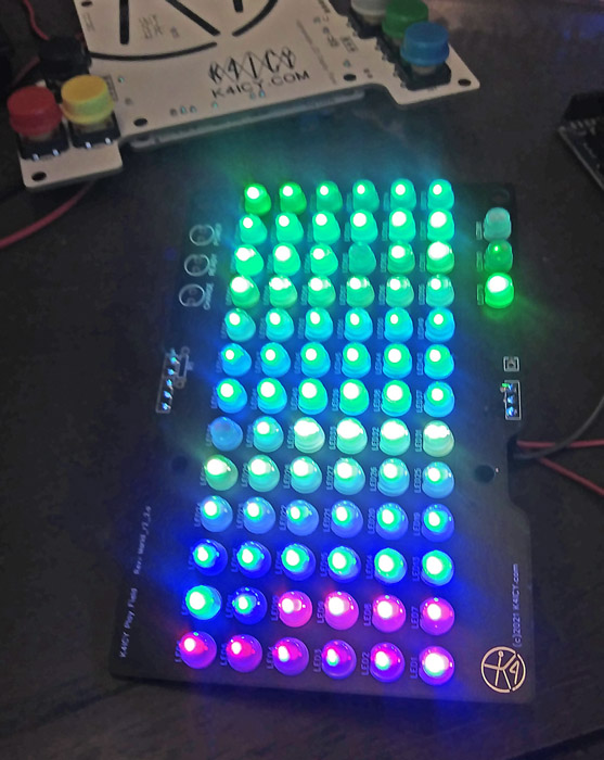 A lighting test of the new Play Field. The advantage of using non-SMD F5 LED's is the ability to replace any failed ones. _ 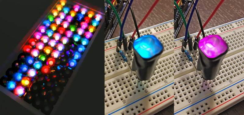 The plan is to use acrylic rhinestones to make each LED take on a 3D jeweled appearance. A tinted screen will mostly obscure the unlit jewels. _ 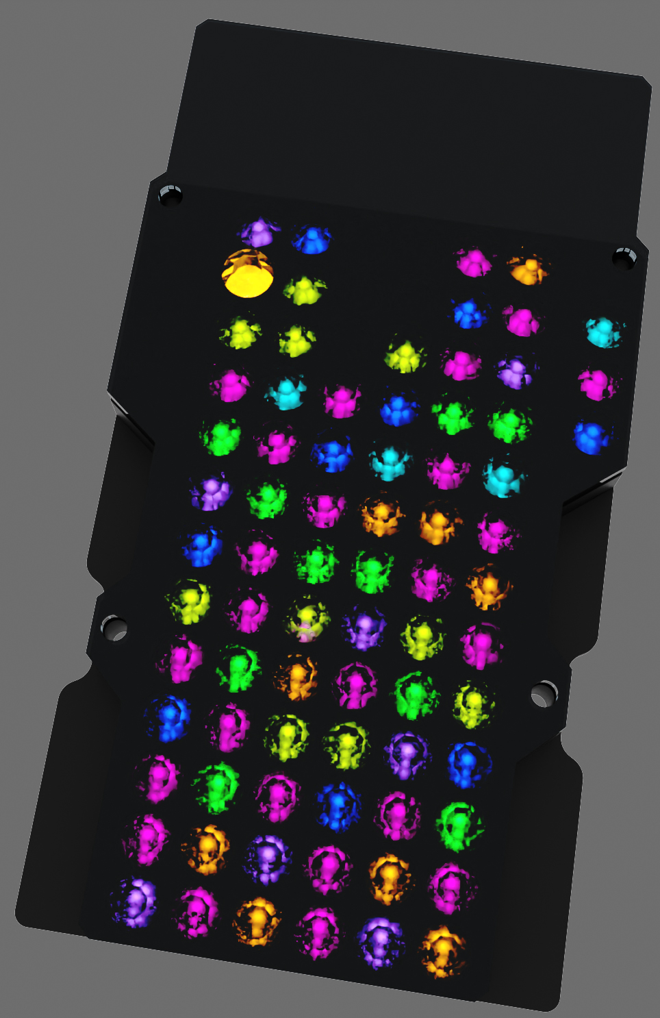
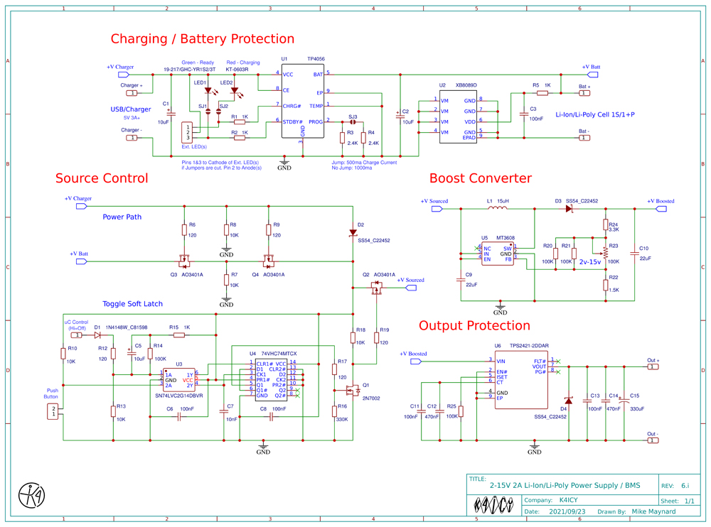
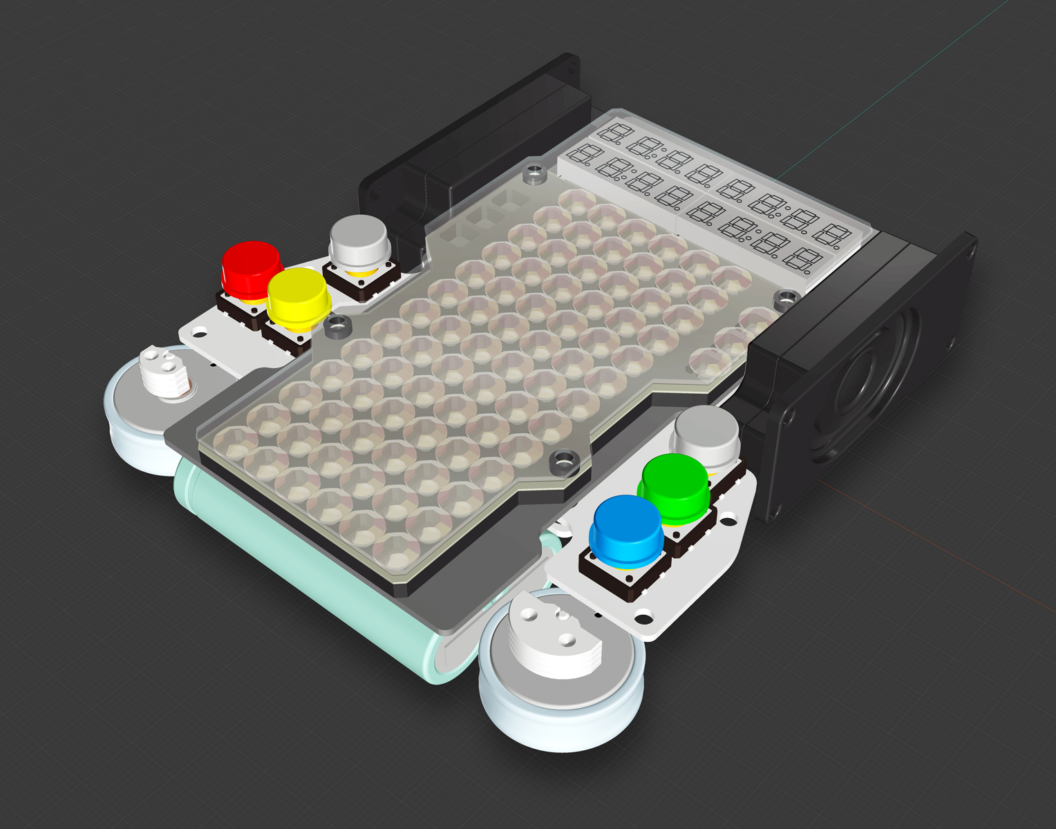
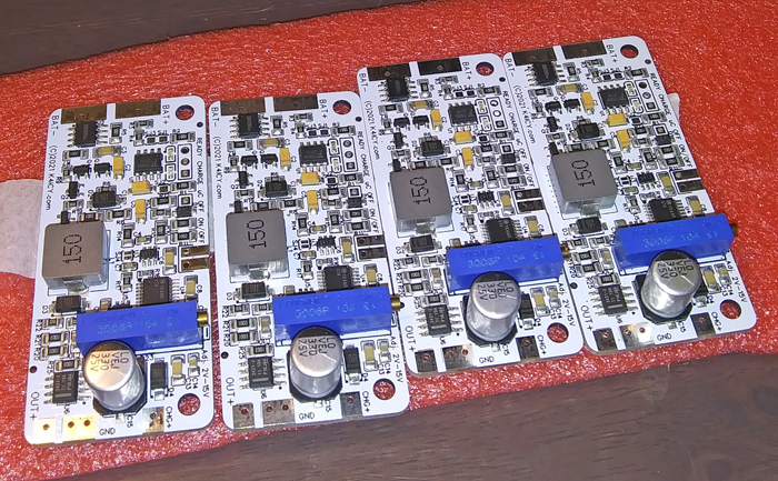
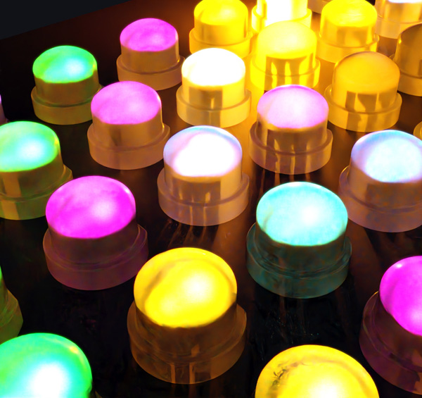 Here are more concept renderings of the Play Field using the WS2811-F5 LED's beneath acrylic rhinestones. _ 7-SEGMENT / 16-DIGIT LED DISPLAY: Why would I spend more than twice as much to replace the perfectly fine "jellybean" numerical display modules I already had in place? Purely aesthetics!The original MAX7219 modules (named for the Maxim LED driver IC) are cheaply mass produce and perhaps fill countless storage bins at many Shin Zin factory outlets like the candy they are. The size was acceptable and with a 5-wire serial connection it makes no sense to use anything else. But for me, a bit of industrial design has gone along with the electrical engineering and the dimensions of the characters (font) used here in my custom build are what I feel to be the appropriate sizing for the final look and feel of the intended product. I felt that the standard 'jellybean' LED digits where a bit too large for my design, and that's it. There has been some reward in designing my own display. JLCPCB did a great job and shipped it to me quickly, as usual! I was actually a bit worried that something wasn't going to work, but EasyEDA, along with their well-established and tested component footprints mostly eliminated the possibility of a wiring error (checking things twice for myself, of course) but I was still concerned about the electrical characteristics; was the current programming (Iset) resistor correct as not to blow out the LED's? Did I mind the actual required wiring of the modules? So, the MAX7219 drivers and associated Arduino library sets digits from right to left and from 0 to 7. The LED display modules are described in their data sheet with digits denoted from left to right and 1 to 4... plus the multiplicity of their wiring. I realized afterwards that I wasn't sure how I managed to get the intended top and bottom characters to actually end up where they should have. I'm still not really happy with this iteration. So, what I have here for now will work just fine in the final build, but I'm hoping to eventually come across white LED versions at the same dimensions. I would like to use a colored "gel" overlay screen on top that tints each row with a gradation fade; like from blue to white to orange, reminiscent of CRT overlays in 1970's arcade games. _ 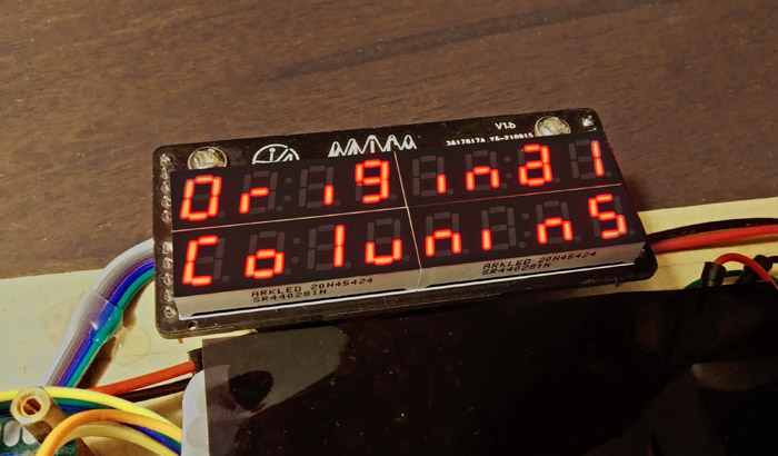 _ I feel that the 'number' segment style font used for these smaller displays are a bit less legible than the ones used on the standard 'jellybean' Amazon/eBay MAX7219 modules, but this nuance is subjective as we can only approximate the appearance of any given letter of the alphabet on a 7-segment numerical formation. Note the use of large and small lowercase characters, "i"s with no dot and "m"s which are made from an "n" plus an additional line from an adjacent digit. I've also made capital "R"s from "A" plus it's decimal to give the appearance of a "R" with its slanted leg. Individually, these pseudo-Alpha character are harder to read but in a group the brain is often good at interpreting the intended word. These are only 7-segment numerical digits of course. _ 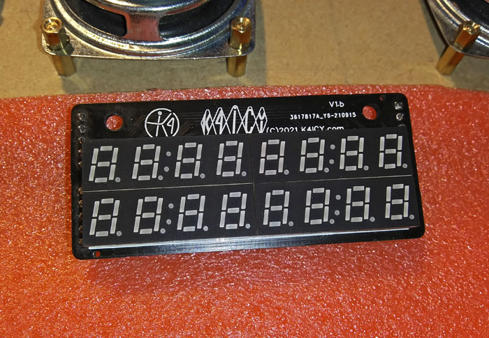 _ The individual LED display modules measure at only 10mm x 32mm with a character height of 7mm. The colons shown on these modules are non-functional as the plastic light guide forms are often interchangeable with other specific factory models. That's unfortunate since I use a counter clock on the Flash Columns game. The spec sheet, though in Mandarin, was pretty clear on dimensions and wiring, so that was understood going in to the project. _ 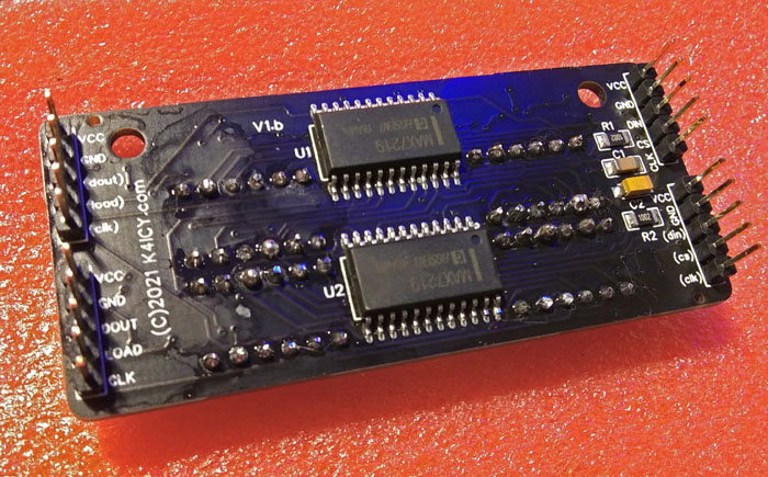 _ Two MAX7219 (actually clones due to the great chip shortage of '21) control a total of 128 individual LED elements. It's a beautiful thing to see 128+ conductor paths reduced to two or three data lines. Four sets of 5-pin (2.54mm pitch) headers mimic that of two stacked common 'jellybean' MAX7219 LED modules and they are likewise spaced and wired, which means both my custom version and the commercially available standard type are equally compatible with my Columns motherboard PCB. Operation and control of the entire display requires only the entry (5-pin) set of header pins (on the upper right as shown above,) the bottom right and upper left are intermediate as they would be if using two standard modules and the bottom left are the exit set which can be fed to more modules if needed for any particular project. Any redundant pins, at the least, can serve as physical supports. The other difference from that of the commercial versions is that the excess area on the sides has been removed down to the near edge of the headers. The width is then at 72mm which is how I will standardize the motherboard and other components. _ MP3 AUDIO: Operation of the DFPlayer Mini MP3 player modules on my game has really been distilled to simplicity. [Please check out the official info: HERE] I'm using Nick Gammon's Send-Only Software Serial library. Nick's GitHub Link HERE... [he also has a Receive-Only version too,] to cue up two separate players; one to do the Sound Effects and the other, the Background Music. Since no return telemetry is required, there are only a few simple set of instructions in the sketch, with help of a function, to get them running, namely; Initialization, Volume, and Song File Cue, each operating independently. Software Serial can be a useful tool for working with multiple Serial-based devices, not being restricted to any particular I/O pins. The good thing is, that there's many online examples. As far as the component circuits are concerned, at least first try building them on a proto-breadboard. You can cue up the DFPlayer Mini's apart from the Arduinos by using their IO inputs, such as contacting IO1 pin (pin 9) to Ground which will start playing tracks, so you can at least test the audio amplifier off-circuit and then experiment with Arduino control As in the photo of my original setup, to make things easy, just start off with only one DFPlayer for just the Sound Effects (device 1,) running only one speaker from the Spk1 and Spk2 pins without the extra components. Pins 6 and 8 will provide enough gain to power a small speaker, but since it uses a bridge mode amplifier, these pins must exclusively connect to the speaker's (+) and (-) connection with NO lines connecting to any Ground path. The Mini's generally come with an 'operating' LED which will give you a good idea on if the Arduino is successful in cuing up tracks. Read [above] again for some detail on how to mount the mp3 files. Issues that cause them grief may include using more than 5 volts, wiring the speaker to Ground, not using a resistor on the Serial line to the player's RX line or using the correct byte-wise commands. Some of the Mini's useful features include, a relatively efficient PWM Bridge-Type audio output port supporting an 8 ohm / 3 watts speaker, 24-bit DAC audio output port which also supports analog audio out (used in this project,) multiple control paths including serial for MCU control and I/O ports for hardware or manual control. The 'AD' Key ports offer quick play access to multiple track as well as pause and play features and the Busy port can be used to detect operation. The mini supports multiple bit/sample rates for playback with a 30-level volume adjustment and 6-level EQ presets. Media formats include Flash FAT16/FAT32 SD cards, U Disk and USB Flash Drives up to 32GB with a read capacity up to 25,500 .mp3 or .wav files. Not bad for an inexpensive device measuring just about an inch square. The DFPlayer Mini module operates at a voltage range between 3.2~5.0 volts, with 4.2 volts being the ideal, and at idle consumes only 20 ma. It is not recommended to run at 5.0 volts, the upper limit, so if possible, employ a voltage regulation method. IF you'll be feeding audio directly to an amplifier, then simply running the (+) supply of the Mini through a 1N4001 diode and the voltage drop will work fine. IF supplying a speaker powered by the Mini, use a buck converter or LDO voltage regulator with an input voltage of at least 7.5 volts due to dropout and efficiency limitations. So, you may notice the use of a regulator in my SMD circuit. Due to it's voltage drop, I end up feeding 3.7 volts to the Mini's, but voltage stability due to increase current is a bit better than with a diode. The stereo audio output from the DAC lines of both devices, along with slight high-end filtering, is fed into a PAM8403 PWM amplifier for output to two small speakers. These IC's come on dirt-cheap modules but if you use the IC's on your SMD build, then you can use the Mute pin to eliminate any strange squeals upon power-ups. Audio file cuing is darned near instantaneous with status on background song completion being provided by the associated player's Busy line. Most of the nearly 350 background songs have some stereo quality built into them and sound effects have been multiplexed to add a 3D quality to game play. _ Please CLICK HERE to check out the BMS project build page! The Columns for Arduino game project has certainly borne fruit beyond its scope, one being the creation of a Lithium-Ion battery controller and power supply for any project requiring 2-15 volts up to 2 amps. The controller can be brought on line at the push of a button and commanded to shut off with any host device. It's this BMS daughter board PCB which had truly made my Columns game portable.The topic of battery management and power supplies can be a bit complex... if you are not planning on making your game portable, just gloss over this section... So, for a bit about my first version: I sized a PCB design around the dimensions of two 18650 Li-Ion cells and manufacture and SMD placement was masterfully done by JLCPCB. Under test, my Columns game setup runs at 5v and (with the current sketch) and typically consumes around 370ma at idle with ~600ma+ of current at peaks. A sufficiently regulated 1,500ma supply will be more than adequate as long as an eFuse or some overcurrent protection is implemented. I generally get around only 3 or so hours of play time on one charge, which is very shy from the estimated 14-28 hours calculated for the 2x3000mwh 18650 cells (1S2P) I'm using. But again, the use of RGB LED's pushing 0.6 amps would tax any small supply. Are you a little confused about 18650 cells? Need help getting started? Please see the following video for a great overview: _ _ My first BMS version employed a Schottky diode in the battery path which killed performance with a (perspectively) huge voltage drop. So, the design goal was to be able to play while the game was charging! The boost converter makes up for it by pulling more watts, which was a calculated risk. But often, you can't really assess a design direction until you see it in action. Charge time took up to 11 hours [charging at 500ma rate] which is insane, but the next revision would use a better-designed circuit and the cells should vastly improve in play and charge times. The next revision charges at a 1000ma rate and should give me more play time as the diode will be dropped for a bidirectional mosfet switch. _ 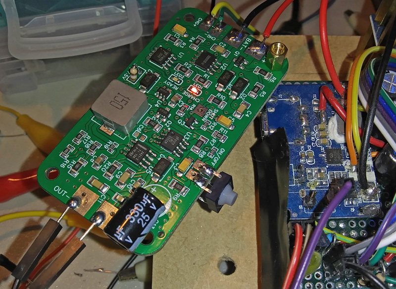 Revision 2.c of the Li-Ion Power/Charging Module shown above. _ 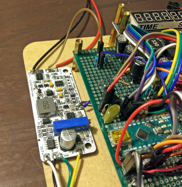
_  Revision 6.h of the of the Li-Ion Power/Charging Module _ FEATURES INCLUDE: • Charging of Li-Ion / Li-Poly Batteries (1S/1P+, or a pack of 2+ in parallel - 18650 cells) and indicator LED's (internal, with external access to chassis-mount LED or uC update) • Safety Features with protection from overcharge, overdischarge, overvoltage, undervoltage, short circuit, overcurrent and reverse-polarity. • On/Off via external single push button and shut-off via microcontroller input. Extremely low quiescent (off-mode) current. • Adjustable output voltage between 2 - 15 volts with typical current sourcing capacity of 2 amps* (at 5v). • Operation of host device during charging cycle - charging cells isolated from host device current draw with minimal interruption during switch-over. I suggest using 2.5A+ external (wall) charger for external power + charging. 1.5A is fine for the Columns game setup. Lithium-based rechargeable batteries are a God-send for modern portable electronics. They pack a ton of energy into a little space with very little weight, which means your awesome Arduino project can last for hours on a single charge, but working with lithium-ion or lithium polymer cells are no light matter. If a cell's packaging is pierced, is allowed to overcharge, overdischarge, short-circuit or too much current is drawn for its designed capacity, the cell can overheat rapidly with an exothermic reaction, be permanently damaged and a violent fire or explosion is a likely result! A Battery Management System (BMS) circuit is a requirement for any project using Li-Ion/Li-Po power and there are a sea of options and parts to choose from. However, you, the DIY builder, may find it hard to find an off-the-shelf solution, and many boards are poorly designed and made for cheap, and exactly what circuit are you to build? If designing and building one from scratch is out of your wheelhouse, safely appropriating an existing circuit from a portable power bank may be a viable solution for your project as a commercial circuit is already matched to the cells and requirements of needed features. You can learn more about what to look for in BMS options here: https://learn.adafruit.com/li-ion-and-lipoly-batteries Adafruit has a comprehensive guide to Lithium-based battery use, particularly for the maker market as well as inexpensive BMS/charging breakout board offerings. A good BMS needs to include a few safety protection features including short-circuit, over-current, over-charge, over-discharge, under-charge, under-voltage, over-heating, cell balancing as well as other considerations. I felt that the easiest route for my project was to 'hack' an existing portable cellphone charging pack (which was made by Jackery.) A few modifications I made to this 2A, "6000"Ahr charger pack included State of Charge (SOC) voltage reading access, full-output power mode and utilization of its integral flashlight feature to act as a game input. Eventually, I omitted the (Flashlight Option) menu access. Many brands will work, so do a search on Amazon or eBay for any phone charger portable battery pack with at least a continuous 2 amp output capacity. Be sure to do your research and study the manuals so that you can avoid a few well-intentioned pitfalls including integral auto-shutoff timers, proprietary phone model exclusivity and too-sensitive of current surge safety shutoff protection. Speaking of capacity, the polymer flat packs work and are lighter but as far as price and capacity the 18650 Li-Ion cells pack the most power for the punch for your projects. Typically, they have a working voltage range between 3.0v - 4.2v but with a nominal voltage of 3.7v present during the majority of the discharge cycle. At full operational discharge, they'll be considered dead by 3.5v. Their nominal capacity, given in mwh (milliwatt-hours) at 1C, can be all over the map but most often, manufacturers way oversell the rating, and in reality, their cells will only provide a fraction of that. _ 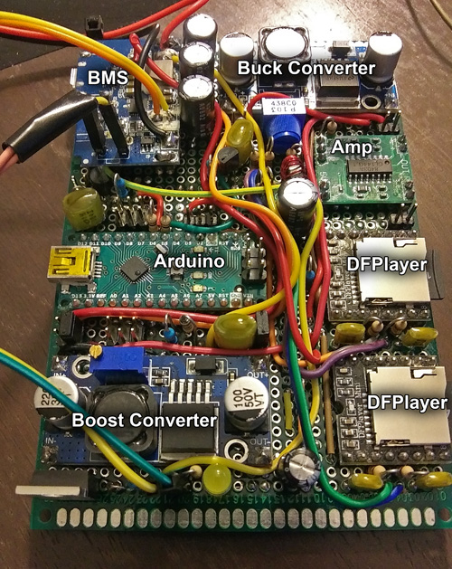 _ To increase the current output capacity of your battery pack it should be safe to connect more cells in parallel as long as they have the same internal resistance, sitting voltage and capacity, and if you need more voltage, then put them in series. Combine parallel packs into series to up the overall voltage and current capacity. If in series, you're required to run them on a BMS which can either account for individual cell balancing or has a protection cutoff circuit. Since you can't really monitor individual cell balancing in parallel packs with the BMS, a thermistor sensor over-heating protection circuit should be integral to the BMS. This measure is what my Jackery BMS uses as it has two cells in parallel. You should also strongly consider purchasing cells from the same lot. You can also consider running each cell through fuses (typical for application) to protect from current runaway due to a failed cell within a parallel pack, because weaker cells will suck the life force from the stronger ones. And again, if a BMS uses a single cell or two in parallel, you can often add more cells in parallel for more capacity if the are matched and from the same manufacturing lot, the only caveat would be that the current protection measures of a particular BMS may determine this feasibility. You do NOT need to take your power bank apart! There's no need, but you won't be able to read the battery level without access to the cells and that feature will have to be disabled in the Sketch. bool batteryShow = false; Simply run power via your USB power brick to your Arduino and other connected modules if you're a bit weary to crack one open... 1) If the power brick already uses thermal protection, the thermistor or thermocouple MUST stay affixed to the surface of the cell(s) within the pack to protect against thermal runaway, more importantly if you are charging or discharging at a rate more than 1C. You can solder extension wires to the BMS board. If you're building your own, study the spec sheet. 2) Many BMS's come with a convenient Flashlight option. If available, in typical models the board supplies current to a white LED when the power button is held for more than 2 seconds. Determine the polarity by observing how the LED is oriented before you de-solder it. If you wish to take advantage of this option as an input method for your Arduino circuit, run new wires to a 5v opto-isolator such as a 4N35. You cannot generally read the leads to the LED on an Arduino as the BMS board may only load power when it detects a need for current from the LED. The signal from the opto can cue up a special feature like a hidden menu or whatever - why not? It's a free control feature. _ 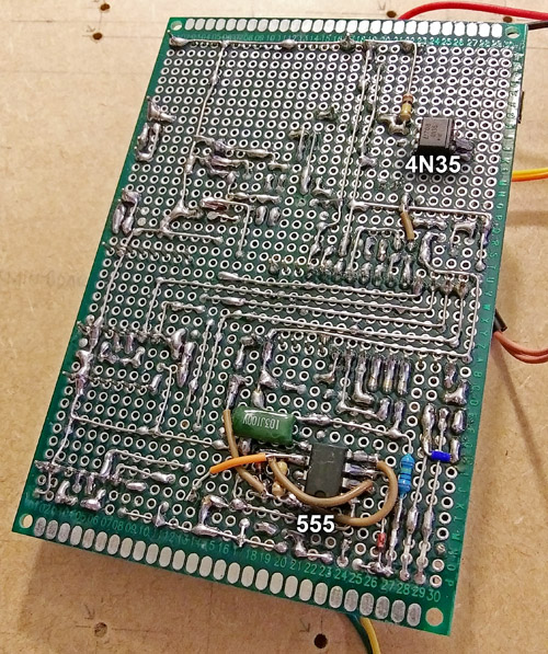 _ 3) Many BMS boards and phone chargers follow a certain protocol to limit or allow a maximum of current to a particular connected phone, usually for component safety reasons (proprietary-use restriction reasons for Apple,) or essentially a "handshake" between the two devices. You can see some info on that HERE. For most devices, if you shunt the Data+ and Data- on the USB output socket on the charger it supposedly will tell it that the device is to act like a "dedicated charger" and allow for the full current amount, which in the case of my Jackery unit is set to 2 amps. 2 amps is the target capacity you should supply to this game. 4) Voltage Reading: This game uses an (Analog) ADC (See appropriate sketch for pin number) and a resistive voltage divider (see schematics) to sample a 10-bit voltage reading from the battery's positive terminal. In most cases, the BMS has a protection device which will disconnect the ground path from the battery via a mosfet if any of its safety conditions are not met. There should be a low-enough impedance path to read its voltage during operation using your microcontroller, but if you cannot, set the "Battery Show" option in the sketch variables section to 'false'. It is often suggested that your resistor divider not use values over 10k due to the requirements of the ADC's internal charge capacitor as erratic and slow readings are likely, however in my testing, using 1M ohm values still works but with only a few caveats. For one, the bottom resistor is now coupled with a bit of small current flow allowed through the ADC, so it's value will be reduced by 10% or 20%. But you can account for that in your conversion calculation. I chose to use two 1M ohm resistors as to reduce the current leakage from the battery, especially when the game is off, to a negligible level. If you wish to get better readings by using lower values, you can consider employing a mosfet to block the connection to the batter when the game is off. To calibrate the sketch for your own build in order to read your battery's voltage, you'll just need a bit of DVM measuring and a tiny bit of math. The Resistive Divider Factor is the ratio actually measured for your (R6/R7 on Mark I / R5/R6 on Mark II) and can be found by measuring the top resistor connected to the ADC pin, and measured while not connected to the battery, then also measuring the bottom resistor while connected between the ADC pin and ground - as mentioned, its value will be lower as, at 1M ohms, there is a lower comparative current bleed through the ADC pin to ground. The Resistive Divider Factor = 1 / ((Bottom Resistor / (Top Resistor + Bottom Resistor)) The User ADC Conversion Factor is derived by first obtaining the (10-bit) ADC reading from the analog pin via a sketch; say, "479" for example. Then take a sample voltage reading of the output of the resistor network at that pin with your DVM; which may be at 1.78v for example. So, The User ADC Conversion Factor = 479 / 1.78 = 269.1 [example only] then the sketche's variable batteryVoltage = (479 / 269.1) * 2.132 = 3.8v, which is what would be measured at the battery terminal (+). Arduino's Map feature would be a great help here. But wait, you say, the ADC 10-bit number should be around 364 for 1.78 volts measured. Yes indeed, if the analog reference voltage was at 5.0v and you can certainly set a physical 5.0 reference at the AREF pin, but on my particular Arduino Nano, which is running at 5.0v (and not 7-12v) the internal Aref at the comparator sits at around 3.85v and not at the Vcc. This is due to drop-out on the Arduino's voltage regulator, but since we are reading only a minute range (BETWEEN 3.5v - 4.2v) from a lithium battery, and we aren't trying to outright establish a State of Charge,so we have some leeway. Drop-out reduction is NOT an issue with a stand-alone AVR chip where the Aref would be at ~5v. When setting this up for your own system, use an adjustable bench power supply to supply a mock typical Li-Ion/Li-Po battery voltage range of 3 to 4.1 volts. 3.9v may typically represent the upper range of a fresh charge considering current-induced voltage drop on the cells, and 3.6v often represents the typical battery-dead threshold for many BMSs Here are some interesting related discussions: https://forum.arduino.cc/t/measuring-approximate-battery-state-of-charge-and-voltage-of-a-lipo-battery/422318/14 https://forum.arduino.cc/t/proper-voltage-divider-for-battery-voltage-detection/398198/20 https://jeelabs.org/2013/05/16/measuring-the-battery-without-draining-it/ [Archived on Wayback Machine, no longer available] https://jeelabs.org/2013/05/17/zero-powe-battery-measurement/index.html [Archived on Wayback Machine, no longer available] You're certainly welcome to write your own function which would tell you the actual voltage, and even better, the State Of Charge or percentage of remaining charge, but as you may know already, lithium batteries don't discharge in a linear fashion as they're designed to give you more play time per charge. This is a difficult thing to read and it is advisable to either use a specialized IC package that can give you expected SOC data, even via I2C, or you could log simplified power dissipation histogram data to the EEPROM which can be used later on to 'train' your Arduino to guess where your battery should historically be dictated by the amount of current consumed over known periods of time. This sounds complicated, but your smartphone does this and there's even often a screen on many phones to show this history. _ 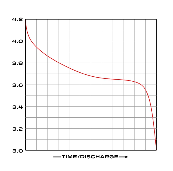 _ Again, we can't just map() the measured min and max and apply that to a percentage because the curve isn't linear. An easier solution is to apply some math, such as a sigmoid curve function (s-curve) to the voltage reading values and hope to get close to a more realistic charge cycle percentage. You'll have to come up with a formula that isn't too complex as to eat up valuable Arduino SRAM, but also close enough to give you the best idea on charge percentage - based on what you've measured during discharge cycles on your battery. Using a charting map based on actual measurements over the entire cycle would be most accurate, but again, that would consume valuable variable memory and battery cells tend to lose capacity over use. If accurate enough, the game user may even be able to know their remaining estimated game-play time before recharging, but the simplest solutions I now use is just to measure the voltage and have the sketch warn you or take action if the voltage goes below something like 3.6v. With all this said, it still must be understood that each Li-Ion cell type, even each individual cell will have some sort of non-uniform power/discharge distribution. It is easier then to just pick a low voltage threshold as indication to the user. _ What's With The Delayed Power-Up on the Mark I Design? Your chosen portable battery system should come with integral over-current and under-voltage protection. As the various components of this game are given power, including the LEDs, power boost/buck converters and audio devices, you'll encounter a current draw spike and subsequent reduction in voltage from the battery pack's regulator. A garden variety phone charger pack BMS circuit will likely go into emergency shut-down or further reduce output voltage as a required safety feature if it is not robust enough. For me, my newest version of my custom BMS is designed for this to hopefully no longer be an issue, but with an off-the-shelf BMS, the simplest solution is to either power on different game modules one at a time or ease them all in gradually. The only major issue from a soft-start would be possible system or data corruption in the Arduino or LED modules. Make sure to clear the displays on startup, and for the most part, the Arduino should be able to survive a short under-voltage condition. This circuit is just an adequate solution to current inrush and can be omitted from your build..._ 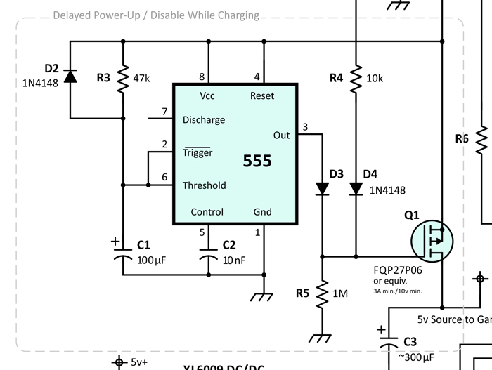
_ Update Log... What has changed in version 7g7 since version 6e5: 1) Many code optimizations, which gained enough memory space to add the extra game along with some cleanup work on the sketch. 2) Added the Flash Columns game! This variation came as a second game option on the Sega Genesis and other console systems as well as the main game on the Columns II arcade cabinet (Sega Astro City and Verses City). 3) Removed the Core Menu. Some functions were made more easily accessible on the main Splash Screen and some were 'baked' into the game. The 4N35 opto-isolator is no longer needed and the 'flashlight' feature of the battery pack isn't utilized. 4) Added 57 background music songs to make a total of 98. The majority are recorded from a few of Sega's platforms for Columns and many renditions from various fans. Most were remastered and edited for artistic variation by myself. The builder may not like them all, but no one can blame this game for sounding too boring.
What has changed for version 7i5: -
Final Sketch for the Mark I Build 1) I finally implemented the auto-shut-off feature. In the Menu mode, no input from the user for 60 seconds will cause the Arduino to tell the BMS latch circuit to shut down. This way, the game can't be left unattended to wear the batteries down. 2) Tweaks to the FastLED parameters to properly use the WS2811-F5 LED's. 3) Tweak to voltage reading code to match the new PCB What has changed in version 7k9:1) Even more code optimizations that notably decreased the sketch's memory use. 2) Before this update, the pre-fill Play Fields for Flash Columns consisted of a multiplexed array of pre-determined patterns that were plotted on random offsets. This was the case with the Sega console and arcade versions and in fact, most of these maps were copied from those sources as they were designed not to be self-collapsing with no match-3 arrangements. I created a new procedure for plotting these random patterns (which contain no match-3 arrangements,) by solving a given random set field by brute force, changing matches out for new random jewels and running the solving process repeatedly until the field is void of match-3 arrangements. Each scan only takes 2 ms a piece. Fields containing 6 to 8 jewel types will solve in 0 to 3 passes while a 3 or 4 jewel setup make take over 2 seconds with over a thousand passes, but the game specific menu has been run as for any long-solution processes to not be noticed by the user. 3) The Button Detection / Game Piece Movement implementation has been rewritten for better debouncing, improved timing and reaction feel, and has been optimized to feel appropriate across the major game speed range. Addressed issues with game piece over-stepping and undesired effect from simultaneous button presses. 4) Tweaks were made for optimal lighting levels of the addressable LED's. 5) Menu optimizations for Menu-Mode user-control for audio and brightness levels. All in all, the Program Memory is now down to 85% and the Global Variables are down to 57%. What has changed in version 8c3: 1) Two new games were added including the 3-minute Time Trial Columns game (from the Sega home console version of Columns) and Crush Columns, a variation of my own creations employing some of the elements from Sega's Columns III game including the Crush Bar, a floor that raises with the intent to push the player's jewels to the top. This makes four games - not bad for an Arduino project! Optimization of some menu system elements were implemented and many variables had to be augmented to tie the underlying mechanics of all games together while allowing for game-specific actions. 2) A Self-Destruct mechanism was added... just kidding. If the user holds down the [LEFT]+[RIGHT]+[ARRANGE]+[DROP] button upon system power-up, the EEPROM will be rewritten with 0's as to wipe the scores and any settings. Especially useful as re-programming the correct sketch via ICSP port is a bit beyond most player's pay grade. So basically a "factory reset" option. What has changed in version 8e1: - Release Candidate for the Mark II PCB Build 1) Reorganization of the MP3 Sound Effects and Music file structure along with a change in the file access mode method for the DFPlayer Mini module. This allowed for the addition for 255 more songs and additional game mode specific tracks. The 255 additional songs including selections from the Tracker/Chip Tune/Installer/Key Gen genre. The Time Trial Columns game has 15 Columns-based songs that were mastered to speed up during game play. An audible count-down timer was also added. 2) Rewriting of the Game Board Display count-down/up clock routine that aligns the count to the AVR's internal pace rather than advancing by event timers. Game play time is now accurately measured for Flash Columns and Time Trial Columns. 3) Fixed a bug where runaway points were added for certain combo scoring events in Crush Columns and would quickly max out the score board. 4) Since the optimal number of separate distinguishable jewel palette colors seems to be around seven, the initial randomization routine for the palette will omit the #8 color unless eight are requested. _ Planned Sketch Tweaks...
I will likely never upgrade
my Columns
game to an expanded memory platform as time has run long for this
project and I'm personally quite pleased with packing so much on an
ubiquitous entry-level AVR, but if I did, perhaps a few new goodies
could be added. And I would leave this to other contributing
programmers. Maybe the ability to link multiple players
together
for a doubles mode, if that would make sense on a single-screen
handheld or even other features between competitors such
as flipping the play screen upside down upon crushing a
"poisoned jewel" or even being able to grey out the competitor's play
field would be fun. A more awesome Splash
Screen and graphics during the pre-game
options cue using those RGB LED's for what they're worth.
Maybe A
leader board and the use of three-letter player initials - if small
14-seg displays are available. And
why
not sneak in a Tetris variant or the ability to rotate the game piece
column into a horizontal or even 'L'-shaped configuration?
How
about linking between multiple game units? But for the
foreseeable future, I just desire to finalize the physical packaging.
_ Versions... Three of four versions of Columns for Arduino by K4ICY have been built:
• Development
- This first phase included everything associated
with
using solderless breadboards and manual DuPont jumper wiring
and
was not portable. I also used a beefy 5v power supply unit.
A standard Arduino Uno R3 was at its heart. This is
the
version that anyone can set up by following my suggestions.
• The
Mark I
- Modules and additional discrete components were
hand-soldered
to a 'proto-boards' used as a carrier surface. This
version was basically a
portable Arduino Nano project mounted to a clipboard but it
was
functional
(playable) and easy to augment for field-trial
and improvement.
This is what any user following along can build with a bit of
soldering and electronics experience.
• The
Mark II
- Functional circuit sections were professionally
manufactured
(SMT/SMD) as modules by JLCPCB and major electrical and programming
issues were solved from the Mark I setup,
and a base physical form-factor
was also established. This
version is applicable as a final product and requires eventual mounting
within a functional finished 3D-printed or injection-molded enclosure.
• The
Mark III
- As still a concept with further miniaturization
and
refinement of
circuits, modules and
component arrangements planned. A few efficiency improvement
would be implemented and the final
product would be made to be 'pocket-sized', perhaps with smaller
addressable LED's,
a more
compact numerical display, improved battery life-vs-size and
other
enhancements including an upgraded microcontroller with added game-play
features. The use of a pseudo-tangible, 3D-feel to the Play
Field
would validate using LED's over OLED or LCD display. The Mark
III
may not be implemented expediently after the Mark II in
lieu of other projects and it would really only serve as a
personal-skill maker muscle flexing exhibition. Form Follows Function... There has to be an exacting interplay between the 3D solid-modeling program, the EDA PCB designer and the real world. There was some back and forth between EasyEDA, CorelDRAW! and Moi3D (Moment of Inspiration). Components can only be packed so tightly and each PCB would have to be fit together, along with actual components including speakers, buttons and etc. and eventually the aesthetics, design language and electronics requirements would have to come to a consensus. At this writing, the PCB's and component configurations are set in stone, but now it is time to give it 'skin'._ A dimensionally-accurate 3D CAD layout of the game's major components was made._ In due time I'll post models in .3DM, .STP, .OBJ and other formats. _ 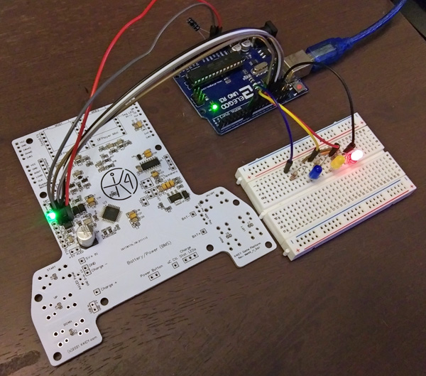 _ The ATMEGA328P-AU microcontroller, implemented (in system) within the game's main board PCB, had to be 'burned' with a bootloader as the IC was fresh from the factory, "blind to the ways of mankind," as the old theologian, the Grandmaster would say. The game sketch could now be loaded actually using the same 6-wire port. See below for info on how to setup and upload programming to a 'vigin' chip... _ The motherboard (carrier) assembly, as shown above. This is the top side of the PCB, which has the SMD components and hosts the BMS and mp3 players. .  The final working assembly with motherboard and attached daughter boards (power and display). Note the addition of various electrolytic capacitors added for power stability issues. . 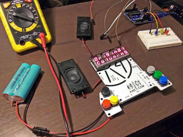
This is the display
carrier side and contains the through-hole
tactile switches. Footprints for two types(sizes) of switches
are
provided on
this PCB. _ Form Follows Function... The plan is to install the final project into an attractive 3D-Printed case of an appropriate aesthetic - maybe something with an ancient Greco-Roman appeal. The more fascinating part will be over the Play Field! I plan on sandwiching several materials to give the appearance of real gemstones floating in the view screen. There is the layer of RGB LED's, of course, but then I could apply a diffuser to spread the light, since the current affect is that of small circles. Next, I would like to add a layer of acrylic gemstones. I own a batch of these already for this project and would like to try filing down the sides and bottom, affixing them together in a grid pattern. Next, will be a layer of dark auto-glass tinting which will hide most everything but the LED light, and finally a layer of scratch-resistant polycarbonate to hold everything in. This tinting and protection will also be extended over the top of the LED Numerical Displays. With everything in the 3D-Printed case, custom laminated decals will be added to give the game a classic commercial look. A fantastic local print shop named Midtown Print Company can handle that well.At this writing, the final form is still in the rough stage and there are a few hardware challenges to deal with. I could use JLCPCB's new Additive 3D Printing Service, but I would rather get my own printer. _ _ HOW
TO UPLOAD THE SOFTWARE: -
On the Mark II Custom Main Board PCB and others Most likely, you'll use the microcontroller by itself without a USB interface like the ATMEGA16U2-MU IC which is integral to the Arduino Uno, Nano, and etc.. As you won't be able to plug up a USB cable and go, you can use an FTDI TTL Programmer (pins are provided on the Main Board PCB) but you'll need to interface with the ICSP (In-Circuit Serial Port) first to establish the bootloader. Please NOTE: your AVR will NOT require a bootloader to be present after the initial burn if it will be used as a stand-alone dedicated device for any subsequent sketches. That will give you a bit more space as well as speed up your microcontroller's boot time, but you do have to burn the bootloader first so that the required fuses and registers are set - and - you'll have to load your sketches through the ICSP port. But whether you wish to establish a bootloader for dev-board use or wish to upload the Columns game sketch to a blank IC (sans bootloader,) it's an easy process! We'll just have to use an existing Arduino board as the middle-man, connecting your target device via its ICSP port. And conveniently, both the initial bootloader and stand-alone sketch can be uploaded via this port. YouTube is a great place to find tutorials on "burning an Arduino bootloader" but check out this video: __ and also read the tutorial provided by Arduino: https://www.arduino.cc/en/Tutorial/BuiltInExamples/ArduinoISP
Follow these steps to use your Arduino as a Programmer:
Make sure to FIRST read Arduino's tutorial for
specific details that may vary from the below simplified step-by-step. > 1) Build indicators as shown here: _ 2) Make connections between the programmer Arduino and the target device as shown: _ 3) In the Arduino IDE choose "Arduino as ISP" (In-System Programmer) under the Tools menu:
_ 4) Open the "Arduino as ISP" Example sketch in your IDE and UPLOAD this to your Arduino which will then make it the programmer:
You should see the "Heartbeat" LED pulsing in and out, indicating that the programmer sketch is running. NOTICE: Make sure the Board: option under the Tools menu reflects the device you're using as a programmer. _ 5) AFTER uploading ArduinoISP sketch - add a 10uF capacitor (between Reset and GND) as shown to disable rebooting of the programmer: _
6)
To FIRST burn the bootloader or if you wish to make a fresh
AVR IC an "Arduino" -
_
7)
After uploading the bootloader, if you wish to directly
upload a sketch to a stand-alone AVR IC -
You may try just not connecting the (+5v) line between the two, only sharing a common ground connection - as long as the voltage of each device is 5 volts. In my circuit, I isolated supply to the AVR IC via a disconnect jumper, but even with that, in a complete circuit, the AVR IC may still unintentionally supply power to connected devices and the current consumption of your target's incorporated circuit may damage your programmer. Consider programming the AVR IC by itself on a protoboard with its associated crystal and capacitors. You should see the three indicator LEDs flashing in various sequences. The Error LED should not stay lit and the Programming LED will now rapidly flash for a bit. The Bootloader install process should take just seconds but uploading a sketch may take more than half a minute. You may also see the "built-in" (pin 13) LED on your target device flashing as well. Wait until the Programming LED has gone off and the target AVR has rebooted before removing the connections and testing. _ NOTE: If you wish to upload new sketches to your custom target Arduino/AVR without clearing or erasing any saved EEPROM Flash data on the AVR IC, consider using the FTDI header if you have designed one in. You will have to have a bootloader resident, but FTDI programmers are cheap and easy to find on Amazon, eBay and BangGood, otherwise, just upload the sketch through the ICSP port. Just remember than a sketch or bootloader upload via ICSP will also wipe all stored data! _  _ SOFTWARE BREAKDOWN: The .INO sketch (ver07j4) Section Locations Reference:
Updated
07/01/25
|
||||||||||||||||||||||||||||||||||||||||||||||||||||||||||||||||||||||||||||||||||||||||||||||||||||||||||||||||||||||||||||||||||||
