.
The Pleasant Code Practice
Oscillator - A Shaped Sine-Wave Oscillator
As Presented in The
Printed Circuit, Newsletter of the Tallahassee
Amateur Radio Society (TARS). December
2012 - Page 12 [CLICK HERE for
NEWSLETTER ARCHIVE]
Many hams that get the electronics or
CW bug
try a Code Practice Oscillator (CPO) kit sooner or later, or maybe
orders a pre-made set, like one offered by MFJ. After a while, anyone
that uses a certain type of CPO will eventually tire of hearing the
harsh tone that comes from it. There’s a good chance the annoying sound
quality is caused by the CPO’s circuit itself. Many such circuits make
use of the venerable and ever-versatile “555” timer IC. It’s not the
IC’s fault but the waveform produced by the circuit that uses it.
Generally what you get is a square wave-based tone that, by
its
nature, sounds raspy, and when keyed on and off abruptly creates sound
artifacts such as clicks and pops.
On top of that, many oscillator
circuits used for CPOs have their main power turned on and off as part
of the keying process which often causes ‘chirps’ and slight
fluctuations in pitch because it takes a split-second to settle the
levels, so to speak. With an abrupt starting and stopping of the signal
you also end up with ‘clicks’ and ‘pops’ and other artifacts. The sound
produced by a circuit with these issues can grate on the hearer’s ears
and actually cause fatigue in longer practice sessions. Real
radios use sine-waves! Since there are practical reasons why your
transceiver uses sine-waves in its operation – why shouldn’t your Code Practice
Oscillator? This circuit may be worth a try.
.
A WARNING ON USING PCB/AMPLIFIED VERSIONS OF THIS CIRCUIT FOUND ON LINE:
.
I've fielded countless emails from unfortunate
builders who used the ProjectAVR PCB version by Steve Smith, G0TDJ,
whereas the circuit DID NOT WORK, either not oscillating or providing
any amplification. I apologize for any inconvenience and
frustration in attempting that circuit, and until I can come up with a
better one, please take the following circuit as an 'educational'
exercise.
If you build Steve's circuit from the following PDF [HERE]
keep in mind that it will not likely work, HOWEVER, you can try
bypassing the transistor amplifier circuit [Q4 & Q5] and feed the
output of C6 (+) to pin 3 of RV2, as with enough gain, the LM386 may be
able to make the signal audible. You may also try placing a
biasing resistor of some value (50k+/-) from that point to +V.
Even though Steve placed my name at the top of the schematic,
this is mainly his modification which happened to reportedly work
according to his setup.
When I can
find time to revise this circuit with good amplification I will be
posting a new schematic and PCB Gerber file(s)..
The following is
my tutorial
for the original version:
 |
A Sinewave
is the purest
expression
of energy on any single given frequency.
A Square-wave is not a pure signal and is composed of odd-integer
harmonic frequencies and thus has a harsher sound quality.
A tone composed of a signwave has a pleasant and smooth sound to human
hearing.
|
.
This ‘Pleasant’ Code Practice
Oscillator produces a smooth-sounding
sign-wave at your favorite frequency, and during keying is turned on and
off with smooth transitions which eliminates ‘key clicks’.
The oscillator is left running constant to reduce ‘chirping’.
I show the complete circuit schematic broken into two parts:
Part
1 – 3-Transistor Audio Amplifier
Part 2 –
Twin-T
Audio Oscillator with Edge Shaping
.
Part 1 – 3-Transistor Audio
Amplifier
. Click on pic
for printable version.
Click on pic
for printable version.
.
You can
build these circuits on a solderless breadboard if you wish.
Also known as a 'solderless prototype board', they’re available on
Amazon, AliExpress, eBay and other sources for little money and consist
of strips of
metal contacts encased in plastic that allow you to plug in wires and
components to build circuits. Without solder they’re reusable,
which means you can build as many circuits as you wish. Just
remember to order your choice for breadboard jumper wires or Dupont
cables.
To see how to use one, check out this site: www.instructables.com/id/How-to-use-a-breadboard/
.
Here
is a
graphical layout of the ‘Pleasant’ CPO on a typical (64x2-row)
breadboard:
.
Click on pic for printable
version.
.
This
3-Transistor audio amplifier can provide a modest amount of volume for
any audio project and doesn’t require many parts. It
was a common design used in some later transistor radio designs and
will provide 100mW of audio power to a 25 ohm speaker. A Small
PM speaker should be used. An 8 or 16 ohm speaker can be used just as
well with down to around 50mW of output. This is a
forgiving circuit and many parts values can be substituted including
the transistors such as using the common 3900-types. Q2 is used
as the pre-amp, and Q1 and Q3 are the speaker drivers. Diodes D1 and D2
are used to create constant bias voltage. R2 can be
adjusted from 50k-500k to peak the transistor’s bias but consider using
heat sinks if the transistors get too warm. Try it once constructed
by applying a very low-volume signal to the input from any audio source
such as an mp3 player. You should get about a 5-times gain factor.
.
Part 2 – Twin-T Audio Oscillator
with Edge Shaping
. .Click on pic for printable
version. .Click on pic for printable
version.
.
The
“Twin-T” oscillator is a classic design. It produces a sign-wave audio signal with very
little distortion by using a complementary pair of high-pass
and low-pass RC filters - shown in the schematic by the two
obvious ‘T’ configurations. C1 and C2 must be the same value, and
C3 must be exactly double the value used for C1 and C2. Just
use two 0.01μF caps tied together in parallel. Adjusting R1 will
change the resonance frequency of the oscillator: A 10k
potentiometer can be used and a value of 3-10k will get you a range of
around 500Hz–1400Hz.
.
 |
Wave-scope
display of a 15wpm ‘dit’ element |
.
You can try any
type of NPN transistor and
there should be enough output to drive a small high-impedance
earphone. The
second part of the schematic shows a common 2N7000 MOSFET and other various
discrete components. Used in this configuration, the MOSFET will
smoothly ‘ramp’ the signal level of the oscillator in and out.
When the ‘Key’ circuit is brought to ground potential through R7, C5
is bled at a fixed rate and Q2 loses gate saturation. The
‘Twin-T’ audio signal is now left untouched. When the
‘Key’ is released, the voltage potential to Q2’s gate is brought to positive
through R6 while re-charging C5 thus the audio signal is now
gradually shunted to ground. R6 and R7’s values are chosen
for around a 10ms transition time.
You can adjust
these to change the attack and decay of the CW envelope. The image above is
an actual wave-scope display
of a 15wpm ‘dit’. The result produces an easy to listen to CW sound and I was able to build
everything on a Radio Shack prototyping breadboard in about
half an hour. Using a breadboard is the next step up
from the spring-terminal project labs that were once offered by
Radio Shack, and they allow you to do so much more. This circuit
can be transferred to a throughhole and soldered Vero prototyping
board and then into a project box. Once finished you can enjoy
hours of smooth and pleasant-to-the-ears CW practice!
. Issues with an imperfect circuit:
There have been reports of both success and
failure with this circuit across the board. When I initially
began working with this CPO, I paired the elegant nature of the Twin-T
oscillator with the brutal one of the LM386 amplifier IC and was
blessed with a code-practice baby with a face only a parent could love.
The output had only enough power to run through a pair of
headphones. The LM386 was fed from the MOSFET shaping circuit
through a decoupling capacitor and it worked pretty well. In
writing this article, I was able to provide two circuits for the reader
to work on, both the oscillator section and a simple 3-transistor
amplifier. The amplifier was just an example in basic transistor
design and wasn't intended to be product-worthy. Steve, G0TDJ,
who hosted a comprehensive STEM course centered around microcontroller
projects, took this design further by adding the LM386 and designing a
PCB. Some have claimed success with his updated CPO circuit and
others have been frustrated by it due to low volume, chirping and
distortion in the final audio.
By standard disclaimer, I can suggest the obvious
by keeping wiring short, using high-quality capacitors and
experimenting with different discrete component values. But in
working with this circuit, I have a few suggestions to consider:
1)
Chirping Tone: When keying, the pitch of the oscillator will
start at one level and quickly go to another rendering a 'chirping'
quality to the sound. This may be due to inadequate
current/voltage regulation to the oscillator section. A builder
may feel tempted to cut the oscillator on and off with the CW key by
doing so directly to the oscillator transistor. To get a
consistent tone you must keep the oscillator 'free-running' so that
it's stable and let the MOSFET sink the audio after the fine capacitor
which decouples the signal source between the oscillator and the
output. Also try isolating the oscillator circuit via a voltage
regulator. If you are running the device at 12 volts, use a 9 volt LDO
regulator, or if supplying at 9 volts, use a 5 volt one.
2) Low
Volume: A common report. Please note that the transistor
amplifier section only provides enough power for headphones or an
earphone and not at much milliwattage. The LM386 should be able
to provide enough to run a 3 to 8 watt speaker - a small one, not a
large PA speaker. You should consider using something for that
requirement such as an LM380. In Steve's adaptation (provided PDF
- SEE BELOW) I feel that the interface between the transistor amp
section and the LM386 could use a bit of work, and I can't be sure as
of yet because I haven't tried it. Try running the output of the
transistor amp into the (-) input, tying the (+) to Vcc, and run this
through a decoupling cap prior to the pot. A 10uF electrolytic
may work. The LM386's input is high impedance but the transistor
circuit was designed to 'work' against a load. A resistor between its
output and Vcc may help. Again, I need to work with this. Resist
the urge to over-gain the LM386. The point of the Twin-T is to
produce a tone without distortion! If volume is still a problem,
try an additional power amp after the LM386 or even try one of those
PAM PWM amp modules you find all over Amazon.
3) Shaping Circuit
Not Working: The MOSFET's gate is capacitive and also a
voltage-driven switch, so play with the associated capacitor/resistor.
Additional wire length on your CW key could affect the MOSFET's
operation, so consider buffering the CW's input with a transistor
switch circuit (used on my Minty Keyer) to isolate the key from the
MOSFET. The MOSFET's only job is to sink the oscillator signal to
ground with an ease-in/ease-out envelope. If a high resistance is
measured between the drain and source when in key-down, then the MOSFET
isn't being switched. .
.
Here
is a
quick and dirty layout on a solderless breadboard.
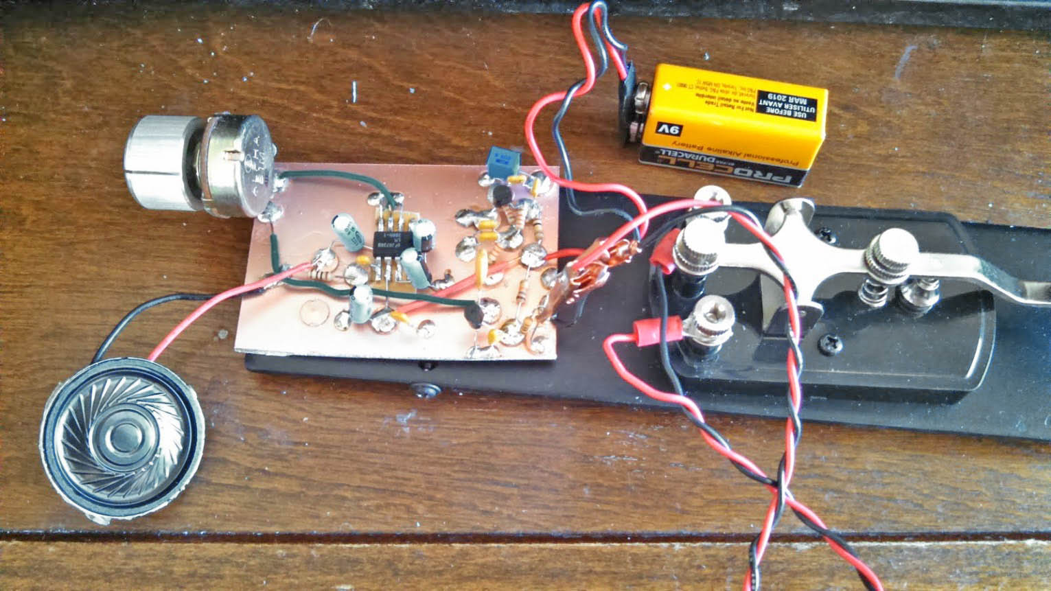
. Check
out this version built by Chris
Waldrup, KD4PBJ
Check
out this version built by Chris
Waldrup, KD4PBJ
.
Chris
incorporated an LM386 audio amplifier and is shown here using the CPO
to get great practice with his newly acquired Vibroplex bug.
Chris
also suggested changing the value of R5 in the oscillator circuit from
a 33k ohm resistor to 100k when using an OP-amp or such type as the
LM386 to reduce audio bleed-through due to too much gain.
.
And
check out this build by Walter
Anderson, AF5WH
.
Walter
also uses an LM386 audio amplifier, and just look at that "Manhattan"
style construction - This is definitely a major upgrade for his old MFJ
Code Practice Key!
.
And again, [READ WARNING AT TOP] here is the updated schematic for the improved version [2.0]
designed by Steve
Smith, G0TDJ:
.
CW_Practice_Oscillator_v2.01_SCHEMATIC.pdf
.
Have some fun
this weekend… For goodness sakes - get out your breadboard
and build something!
73! DE Mike, K4ICY MikeK4ICY@gmail.com
Edited: 06/27/25
(C) 2012, 2018, 2025 Copyright - Michael A. Maynard |
 Practical Electronics
Projects By Mike, K4ICY
Practical Electronics
Projects By Mike, K4ICY 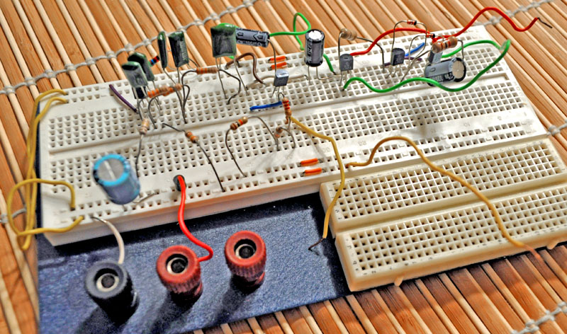